
Network Card User Manual


MRV Communications, Inc. – Installation Manual
30
2.
Received power
100 < OPTICAL POWER < 1000
Expected Results
The BER must be less than 10E-12 (10
-12
) for on-going tests and error-free for
short tests.
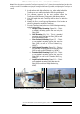
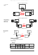
2. TS700/100
Proper Display
2.
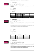
Indicators
Indicator →
AIR RX 100baseT
Position ↓
Flag TX Flag TX
Alignment Loopback
ON
x x x x
OFF
x x
Table 8: Indicators
3.
Received power
100 < OPTICAL POWER < 1000
Expected Results
The BER must be less than 10E-12 (10
-12
) for on-going tests and error-free for
short tests.
The PING test and file transfer procedure should not post any TIME OUT alarm
or last too long time so long as the cabling connection is OK.
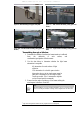
3. TS700/G
Proper Display
3.
Indicators
Indicator →
AIR RX Electrical
Position ↓
Flag Laser Enabled Flag
ON
x x x
OFF
Table 8: Indicators
4.
Received power
100 < OPTICAL POWER < 1000
Expected Results
The BER must be less than 10E-12 (10
-12
) for on-going tests and error-free for
short tests.
The PING test and file transfer procedure should not post any TIME OUT alarm
or last too long time so long as the cabling connection is OK.