
Network Card User Manual


MRV Communications, Inc. – Installation Manual
43
Fi
g
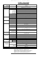
. 6.15a and 6.15b: Ali
g
nment screws
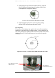
Repeat this process for the vertical positioning (middle of segment [V1,V2]).
H1
H2
V1
V2
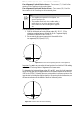
Once the position is reached, tighten firmly the 4 Fine Locking Screws
(2xF2, 2xF1 and G1).
Repeat this procedure interchanging roles with the second installer at the
opposite site, i.e., the second installer will move the remote transceiver
while the first installer will report the digital readout at his end).
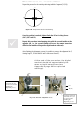
After finishing the alignment process it’s possible to remove the alignment kit (2
Aiming Lugs E1, E2 and Bolts K and D and screws B and C).
At the end of the procedure, the digital
readout should be approximately the
same on both transceivers (see
Appendix B page 44 for expected
readings).
(
Figure 6.14: Final position after the vertical aiming
F1
G1
C
D
F2
K
B (x2)
E2 (and 2 screws
‘C’and 2 bolts ‘D’)
can be removed after
finishing the
alignment process.
E1 (and 2 screws ‘B’
and 2 bolts ‘K’) can
be removed after
finishing the
alignment process.