
Network Card User Manual


MRV Communications, Inc. – Installation Manual
55
TereScopes Bench Test Procedure
Introduction
All TS Products are bench tested indoors prior to outdoor
installation to ensure that the system is fully functional.
The bench test is a simple procedure whereby a link pair is aligned
on the table and activated to simulate a channel of communication
(see fig.1).
2 Points to Remember
1. Since the link distance during the bench test is very short (i.e. the
devices activated are very close), the receivers will go into saturation
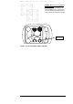
unless the signal is attenuated. (NOTE: In the 700/G, deep into
saturation the DVM reading may actually drop back down, giving
the false impression that the link is misaligned. It is therefore
vital to place the attenuator in the link path before optimizing
alignment.)
To avert entering saturation, the transmit signal must be physically
attenuated.
We recommend the simple procedure of inserting a piece of paper
or the like into the beam path, or concealing a portion of the beam
with an opaque (non-transparent) material. This will reduce the
signal power entering the receiver.
Make sure to attenuate the signal enough so that the receiver’s
optical power meter value falls below the saturation estimate of the
device. See table below for saturation estimate.
2. An additional derivative of the short link distance is the presence
of reflections.
The signal will reflect off the front window of the receiver back at
the transmitting device and may be mistaken as part of the opposite
transmission.
This interference is commonly called “cross talk”.
To avoid cross talk during the bench test, it is advisable to check
whether interfering reflections exist by shutting off power to one
device and verifying that the optical power meter reading in the
other (active) device is zero.
This should be repeated for the opposite device.
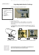
Alternatively, a practical setup for bench testing the 4” series
(models B, C and D) and Light series (models A and C2) is
presented in Figure 1; the bench test setup for the 10” series
(models E and F) is presented in Figures 2a,2b.
In the 4”/Light setup, a thin physical barrier, such as a piece of
cardboard, is used as a wall to divide between the beam paths, thus
ensuring that no cross talk occurs.
In the 10” setup, the two devices are not centrally aligned; instead,
only one corner of each device faces the opposite device. This
APPENDIX E