
User's Manual


• Shut off power to the automatic door before wiring sensor.
• Always ensure wiring is located clear of any moving door parts to avoid
damage.
• Always be aware of pedestrian traffic. Keep people clear of the work area
when setting up or testing the door.
• Comply with all applicable building codes and safety standards (ANSI
A156.10).
Sensor Mounting:
1. Remove the cover of the microStar by placing the blade of a small screwdriver in
the notch in the right side of the cover as shown (B). Once the sensor is attached
to the header always remove the cover in this same manner.
(B) Cover Removal Diagram
2. Attach the mounting template as shown (C) flush with the bottom edge of the
header. Drill 3 holes noted on template (1 wire passage hole, 2 screw pilot holes)
(C) Mounting Template Diagram
3. Insert mounting screws partially into holes. Route the wire harness along sensor
backplate as shown (D). Feed the stripped end of the wire harness through the
wire passage hole. Install the microStar onto the mounting screws and tighten.
(D) Wire Harness Diagram
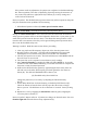
Sensor Wiring:
With power OFF, connect sensor wiring to the operator control as shown (E). Two
wiring options are available. The activation relay output and safety relay output wires
of the microStar can be connected to the activation input of the operator control
(safety will be on at all times) OR the microStar’s activation relay output can be
connected to the activation input of the operator control and the microStar’s safety
relay output can connect to the safety input of the operator control (safety will be off
when door is closed).
(E) Wiring Diagrams
Wiring to operator control’s activation input only:
Wiring to operator control’s activation and safety inputs:
Warning w/symbol: DO NOT APPLY POWER TO THE SENSOR!
Sensor Settings and Adjustments:
All settings and adjustments can be made via the microStar main circuit board so there is
no need for costly or confusing proprietary set up devices.