
User's Manual

8701 Castle Park Drive Indianapolis, Indiana 46256
Telephone: (800) 842-2545/(317) 842-2545 www.mssedco.com custsvc@mssedco.com
Page 1
S-TRXv0312
Section 1
General Description
ClearPath Spectrum radio control transceivers provide
reliable activation of any automatic door, and feature
several industry firsts. ClearPath Spectrum products
feature digital two-way communication, increasing
security and allowing users to pair transceivers to
coordinators, and monitor battery power. With the ability
to identify transceivers by location, optional
SecureActivation will require users of the outside switch
to be granted clearance before activation can occur.
S-TRX = Spectrum Transceiver with 1020 Square
Mounting Box - replaces CP/TX
S-TRX-R4 = Spectrum Transceiver with 1025 Round
Mounting Box - replaces CP/TX-R4
S-TRX-R6 = Spectrum Transceiver with 1030 Round
Mounting Box - replaces CP/TX-R6
S-TRX-J = Spectrum Transceiver with 1010 Jamb
Mounting Box - replaces CP/TX-J
ClearPath Spectrum products operate at 2.4 GHz, making
the wave length more than 5 times shorter than
commonly-used frequencies. Shorter waves pass
through cracks and barriers easier, and transmitters will
continue to attempt to contact the coordinator until it
receives an acknowledgement.
Section 2
Basic Installation
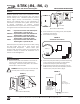
1) Remove the 1/4-20 screw located in the bottom of
the frame and separate the back plate from the
frame (Fig.1). Secure the back plate in its intended
location with at least 2 screws.
WARNING: Mounting screws must be flush with
the back plate to ensure proper assembly.
FIGURE 1
(Front View: S-TRX Shown)
(Rear View: S-TRX Shown)
2) Place coordinator into pairing mode. (See CS/COR
coordinator instructions)..
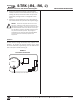
3) Press PAIR button (Fig.2).
FIGURE 2
Transmitter Circuit Board
4) Attach the push plate switch (purchased separately)
to the mounting box frame with the 6-32 screws
provided with the push plate switch (Fig.1).
5) Plug the 2-lead transmitter wire harness onto the
COM (Common) and N.O. (Normally Open) contacts
located on the push plate switch (Fig.3).
FIGURE 3
!
BACK PLATE
1/4-20 SCREW
PUSH
PLATE
SWITCH
PUSH
T
O
OPEN
FRAME
S-TRX (-R4, -R6, -J)
Spectrum Transceiver with Surface Mouting Box INSTALLATION INSTRUCTIONS
h Clear Pat
™
MICRO-SWITCH
UL LISTED
SPDT, Momentary
RATED: 15A @ 125V A C
COM
N.C.
N.O.
Rubber Bellows
Insert rubber bellows
over spring on
exterior switches for
weather tight fit!
BACK PLATE
FRAME
PUSH PLATE SWITCH
LOCK LIP
1/4-20 SCREW
TX PCB
Battery
Battery
Battery 1
PAIR