
Installation Owner's manual


M S D I G N I T I O N • w w w. m sd ig ni ti on .c om • ( 91 5) 8 5 7- 52 00 • F A X (9 15 ) 85 7- 33 4 4
MSD Programmable Fuel Booster
PN 2351
Parts Included:
1 - Programmable Fuel Booster, PN 2351 1 - Software CD 1 - Parts Bag
1 - Harness 1 - USB Cable
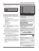
Figure 1 Recommended Wiring, General Application.
USB PORT
ALERT LED
ORANGE
CUT
FACTORY 12 VOLTS
FROM INERTIA SWITCH
RED
1/8” DIAMETER VACUUM
HOSE TO INTAKE MANIFOLD
RED
BLACK
FUEL PUMP +
INDICATES CONNECTION
X
The Programmable Fuel Pump Booster will increase the voltage to the fuel pump in proportion to manifold
boost pressure. The maximum voltage output is 22. The minimum output will be the battery voltage.
Note: It is recommended to have the Service Manual for your vehicle to identify the original wiring and fuel
pump relay.
RATING: Continuous Power: 275 Watt, Peak Power: 375 Watt (one minute)
INSTALLATION
The MSD Fuel Pump Booster must be wired inline with the factory fuel pump relay. The factory has safety
features built in, such as an inertia switch and high pressure shut-off which must be retained.
The MSD Fuel Pump Booster can be mounted in any position and is completely potted with a polyurethane
compound for vibration resistance. Keep the unit away from direct engine heat sources and make sure all
of the wiring reaches their connections. Also, allow access to the USB port.
Use the unit as a template and mark the mounting holes. Remove the unit and drill the holes using a 3/16"
bit. Mount the unit with the
supplied screws. With the
unit mounted, route the wiring
to their connections. Also
connect the boost pressure
line to the booster and intake
manifold (Figure 1).
ORANGE (18-GAUGE, long)
OEM Fuel Pump Power (12V)
WIRING
RED (12-GAUGE, long)
RED (12-GAUGE, short)
BLACK (12-GAUGE, short)
Pump (+) Positive lead to Fuel Pump
Battery (+) 12V
Battery (-) Ground