
Installation

INSTALLATION INSTRUCTIONS 3
M S D • W W W . M S D P E R F O R M A N C E . C O M • ( 9 1 5 ) 8 5 7 - 5 2 0 0 • F A X ( 9 1 5 ) 8 5 7 - 3 3 4 4
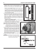
Figure 5 Wiring the Starter.
BATTERY
+
-
LENGTH
3’ 5’ 7’ 10’ +10’
AWG
4
2
1
0
00
CABLE LENGTH VS. GAUGE
12-GAUGE MINIMUM
TO IGNITION
SWITCH
INSTALLATION INFO
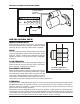
INSPECT PINION GEAR
After cranking the engine several times, you can inspect
the witness pattern on the pinion gear. The pattern should
show 1/4" to 3/8". If over, the internal shim is required.
NOISE
If there is a high pitch whine during cranking, the pinion to
ring gear engagement may be out of specification, on the
high side. If there is a whine after cranking there may be
too little of clearance. The gear mesh spec is .020"-.035"
(Figure 4).
SLOW CRANKING
The most common cause is due to low input voltage. The
battery should be checked, but also inspect the battery
wires, terminals, connections or switches.
DISCONNECT SWITCHES
Most sanctioning bodies require an emergency disconnect
switch. Be sure to use a heavy duty switch that is capable
of handling high current. Some starters may pull over 700
amps while cranking. Most disconnect switches are rated
at continuous and intermittent amps. Make sure to use a
switch that exceeds your starting and electrical system requirements.
R-TERMINAL
On older vehicles, mostly with breaker points, there was an extra terminal and wire on the original starter
(the MSD Starter does not have this terminal). This extra terminal served as a ballast resistor bypass.
When the starter was cranking, 12 volts would be supplied on this terminal and directly to the coil
positive terminal for starting assistance.
Most ignition systems today do not need this terminal, however, if your ignition has no voltage when
cranking you can wire a system. Connect a 10A/250V diode in-line with the motor side of the solenoid.
The banded end of the diode goes away from the starter. This allows current to go to the ignition coil
during cranking and will not feed back to the starter while the engine is running.
Figure 6 Pinion Gear Pattern.
THE CORRECT PINION DEPTH
SHOULD MEASURE 1/4” to 3/8”.