
Installation Manual

WARNING: Disconnect the battery during installation. When disconnecting the battery, always
remove the negative cable first and install it last.
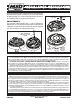
Figure 2 Washer Installation.
MSD Rotor, PN 84211
Adjustable Two Piece Rotor
(For use in place of PN 8467 Rotor)
Parts Included:
1 - Rotor Base
1 - Rotor Top Assembly
1 - Rotor Phasing Tech Brief
The Adjustable Rotor is for use with MSD Distributors using the PN 8437, PN 8433, PN 8431, PN 84333 or PN
84313 Caps. The two piece Rotor provides up to 40° (+/- 20°) of adjustment to achieve proper rotor phasing.
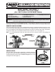
IDENTIFY ROTOR SCREWS
There are two different length screws supplied with this rotor. It is important to determine which screws
are correct for your application due to clearance of the magnetic pickup. There are two styles used;
one is a threaded base with or without a Screw Retainer, the other is a Retainer with a Nut. The Retainer
accepts the shorter 5/8” screw while the Nut version accepts the 3/4” screw (Figure 1).
Note: It is recommended to install the rotor and check the clearance before reassembling the
distributor.
INSTALLATION
Once the rotor screw length is determined, install the rotor base
being sure the round and square aligning pegs are lined up correctly.
Install the Belleville washers with the dome facing up on the screws
and tighten the rotor (Figure 2).
Figure 1 Determining Rotor Screw Length.
ROTOR SCREW
RETAINING NUT
USE 3/4"
SCREW
2 - 5/8" Phillips Head Screws
2 - 3/4" Phillips Head Screws
3 - Belleville Washers
1 - 5/16" Phillips Head Screw
DOME MUST
FACE UP
ROTOR SCREW
RETAINER OR
THREADED BASE
USE 5/8"
SCREW
M S D • W W W . M S D P E R F O R M A N C E . C O M • ( 9 1 5 ) 8 5 7 - 5 2 0 0 • F A X ( 9 1 5 ) 8 5 7 - 3 3 4 4