
Installation Owner manual

M S D I G N I T I O N • w w w. m sd ig ni ti on .c om • ( 91 5) 8 5 7- 52 00 • F A X (9 15 ) 85 7- 33 4 4
MSD Digital Retard Control
PN 8975
IMPORTANT: Read the Instructions before attempting installation.
Parts Included:
1 - Retard Control, PN 8975
4 - Mounting Screws
Note: The Digital Retard Control must be used with an MSD 6, 7, 8 or 10 Series Ignition Control. Do not use
solid core spark plug wires.
OPERATION
The MSD Digital Retard Control uses a high speed RISC microcontroller to control the timing output
signal. This controller can make extremely quick compensations to the output signals while keeping timing
accuracy to within 1°. The circuits are thoroughly debounced and isolated to create protection against
Electro Magnetic Interference (EMI).
There are four stages of retard that can be activated independently or together for a total sum of retards.
Each stage is adjustable from 0° - 9°. The maximum amount of retard is 20° even if the total of the stages
is more. There is also an optional start retard circuit that can be programmed for 5°, 10°, 15° or 20°.
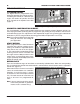
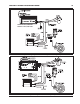
MOUNTING
The Digital Retard Control can be mounted under the hood, but should be away from direct engine heat
sources. Make sure all of the wiring reaches their connections. Use the unit as a template to mark the
location of the mounting holes. Remove the unit and drill the holes using an 1/8” drill bit. Use the supplied
screws to mount the Control.
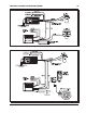
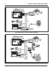
WIRING
RED
This is the On/Off wire. Connects to switched 12 volts.
BLACK
Connects to Ground.
YELLOW
Trigger output. Connects to the MSD Ignition's White Wire.
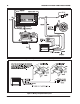
TRIGGER INPUTS
WHITE
There are two input trigger circuits. The wires will never be connected at the same time.
Connects to points or the amplifier trigger wire.
GREEN/VIOLET
2-Pin Connector
Connects to the magnetic pickup of the distributor or crank trigger. Green is
negative, Violet is positive.
BROWN
Retard 1, Activated when removed from ground.
RETARD CONTROL WIRES
ORANGE
Retard 2, Activated when removed from ground.
GRAY
Retard 3, Activated when removed from ground.
DARK BLUE
Retard 4, Activated when removed from ground.
When more than one channel is activated at a time, the retard amounts are cumulative (Example:
4° on the first stage, 3° on the second and 3° on the third, equal a total of 10°). The total amount
of retard that can occur is 20° even if it is programmed for more.
Note: If you are not using all of the retards, set the rotary dial to 0° or ground the inactive
circuit's activation wire(s).