
Instruction manual


Hardware Setup
2-17
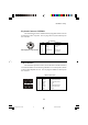
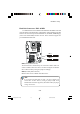
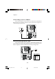
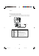
Front Panel Connector: JFP1 or JFP2
The mainboard provides one front panel connector for electrical connec-
tion to the front panel switches and LEDs. Users can choose either the JFP1 or
the JFP2 depending on their needs.The difference between JFP1 & JFP2 is that
JFP2 is compliant with Intel
®
Front Panel I/O Connectivity Design Guide.
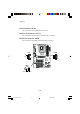
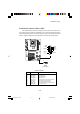
JFP1
Power
Switch
Power
LED
Reset
Switch
HDD LED
+
Speaker
Buzzer
(short
pin)
10
11
1
8
JFP2
(Intel spec)
1
2
9
10
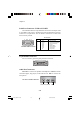
PIN SIGNAL DESCRIPTION
1 HD_LED_P Hard disk LED pull-up
2 FP PWR/SLP MSG LED pull-up
3 HD_LED_N Hard disk active LED
4 FP PWR/SLP MSG LED pull-up
5 RST_SW_N Reset Switch low reference pull-down to GND
6 PWR_SW_P Power Switch high reference pull-up
7 RST_SW_P Reset Switch high reference pull-up
8 PWR_SW_N Power Switch low reference pull-down to GND
9 RSVD_DNU Reserved. Do not use.
JFP2 Pin Definition
Kap2_6547v1.1.P65 05.02.02, 09:3617