Preface Copyright This publication, including all photographs, illustrations and software, is protected under international copyright laws, with all rights reserved. Neither this manual, nor any of the material contained herein, may be reproduced without written consent of the author. Version 5.0 Disclaimer The information in this document is subject to change without notice.
ii Declaration of Conformity This device complies with part 15 of the FCC rules. Operation is subject to the following conditions: • • This device may not cause harmful interference, and This device must accept any interference received, including interference that may cause undesired operation. Canadian Department of Communications This class B digital apparatus meets all requirements of the Canadian Interference-causing Equipment Regulations.
iii TABLE OF CONTENTS Preface i Chapter 1 1 Introducing the Motherboard 1 Introduction................................................................................................1 Features.......................................................................................................2 Motherboard Components.......................................................................4 Chapter 2 7 Installing the Motherboard 7 Safety Precautions.....................................................
iv Advanced Chipset Features.........................................................31 Integrated Peripherals.................................................................33 Power Management Setup...........................................................35 PNP/PCI Configurations.............................................................38 PC Health Status..........................................................................39 Frequency/Voltage Control.............................................
1 Chapter 1 Introducing the Motherboard Introduction Thank you for choosing 845PE-A800 motherboard of great performance and with enhanced function. 845PE-A800 motherboard carries a ATX form factor of 305 x 204 mm. 845PE-A800 supports Socket 478 Pentium 4 processors with system bus speeds up to 800 (overclocking, requires using DDR400)/533/400MHz. 845PE-A800 incorporates chipset of Intel 845PE Northbridge and ICH4 Southbridge.
2 Features Processor This motherboard uses a mPGA 478-pin socket that carries the following features: • Accommodates Intel P4 Willamette/Northwood/Prescott 478-pin CPU • Supports a system bus (FSB) of 800*(overclocking)/533/400 MHz (*A CPU with 800MHz FSB requires using DDR400) Chipset Intel’s 845PE(MCH) Northbridge (NB) and 82801DB(ICH4) Southbridge (SB) chipsets are based on an innovative and scalable architecture with proven reliability and performance.
3 Onboard LAN (optional) The onboard LAN chip is incorporated in the chipset providing the motherboard with 10/ 100 Mbps fast Ethernet controller and integrated Ethernet PCI LAN capabilities.
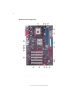
4 Motherboard Components Introducing the Motherboard
5 Table of Motherboard Components 1 2 3 4 5 6 LABEL CPU Socket CPUFAN1 CASFAN1 DIMM1~DIMM2 ATX1 FDD1 COMPONENT mPGA478 socket for Intel P4 CPU CPU cooling fan connector Case cooling fan connector 184-pin DDR SDRAM slots Standard 20-pin ATX power connector Floppy disk drive connector 7 IDE1 8 IDE2 9 JP3 10 JP1 11 PANEL1 12 AGP1 13 USB3 14 SPEAKER1 15 CNR1* 16 PCI1~PCI5 17 CDIN1 Primary IDE connector Secondary IDE connector BIOS flash protect jumper Clear CMOS jumper Front Panel switch/LED header Accele
6 Memo Introducing the Motherboard
7 Chapter 2 Installing the Motherboard Safety Precautions • • • • • Follow these safety precautions when installing the motherboard Wear a grounding strap attached to a grounded device to avoid damage from static electricity Discharge static electricity by touching the metal case of a safely grounded object before working on the motherboard Leave components in the static-proof bags they came in Hold all circuit boards by the edges.
8 Do not over-tighten the screws as this can stress the motherboard. Checking Jumper Settings This section explains how to set jumpers for correct configuration of the motherboard. Setting Jumpers Use the motherboard jumpers to set system configuration options. Jumpers with more than one pin are numbered. When setting the jumpers, ensure that the jumper caps are placed on the correct pins. The illustrations show a 2-pin jumper. When the jumper cap is placed on both pins, the jumper is SHORT.
9 Checking Jumper Settings The following illustration shows the location of the motherboard jumpers. Pin 1 is labeled. Jumper Settings Jumper Type Description 3-pin CLEAR CMOS JP1 Setting (default) 1-2: NORMAL 2-3: CLEAR CMOS Before clearing the CMOS, make sure to turn the system off.
10 Connecting Case Components After you have installed the motherboard into a case, you can begin connecting the motherboard components. Refer to the following: 1 2 3 4 5 6 Connect the CPU cooling fan cable to CPUFAN1. Connect the case cooling fan connector to CASFAN1. Connect the case speaker cable to SPEAKER1. Connect the case switches and indicator LEDs to the PANEL1. Connect the standard power supply connector to ATX1. Connect the auxiliary case power supply connector to ATX12V.
11 ATX1: ATX 20-pin Power Connector Pin Signal Name Pin Signal Name 1 2 +3.3V +3.3V +3.3V 11 12 3 Ground 13 Ground 4 +5V 14 PS ON# 5 6 7 8 9 10 Ground +5V Ground 15 16 17 18 19 20 Ground Ground Ground PWRGD +5VSB +12V -12V -5V +5V +5V ATX12V: ATX 12V Power Connector Pin Signal Name Ground 1 2 3 4 Ground +12V +12V Front Panel Header The front panel header (PANEL1) provides a standard set of switch and LED headers commonly found on ATX or micro-ATX cases.
12 Power/Sleep/Message waiting LED Connecting pins 2 and 4 to a single or dual-color, front panel mounted LED provides power on/off, sleep, and message waiting indication. Reset Switch Supporting the reset function requires connecting pin 5 and 7 to a momentary-contact switch that is normally open. When the switch is closed, the board resets and runs POST. Power Switch Supporting the power on/off function requires connecting pins 6 and 8 to a momentarycontact switch that is normally open.
13 CPU Installation Procedure The following illustration shows CPU installation components. 1 2 3 4 5 Install your CPU. Pull up the lever away from the socket and lift up to 90-degree angle. Locate the CPU cut edge (the corner with the pin hold noticeably missing). Align and insert the CPU correctly. Press the lever down and apply thermal grease on top of the CPU. Put the CPU Fan down on the retention module and snap the four retention legs of the cooling fan into place.
14 Table A: DDR (memory module) QVL (Qualified Vendor List) The following DDR400 memory modules have been tested and qualified for use with this motherboard.
15 Installation Procedure Refer to the following to install the memory modules. 1 2 3 4 5 6 This motherboard supports unbuffered DDR SDRAM only. Push the latches on each side of the DIMM slot down. Align the memory module with the slot. The DIMM slots are keyed with notches and the DIMMs are keyed with cutouts so that they can only be installed correctly. Check that the cutouts on the DIMM module edge connector match the notches in the DIMM slot.
16 IDE2: Secondary IDE Connector The second drive on this controller must be set to slave mode. The cinfiguration is the same as IDE1. IDE devices enclose jumpers or switches used to set the IDE device as MASTER or SLAVE. Refer to the IDE device user’s manual. Installing two IDE devices on one cable, ensure that one device is set to MASTER and the other device is set to SLAVE. The documentation of your IDE device explains how to do this. About UltraDMA This motherboard supports UltraDMA 100/66.
17 Installing Add-on Cards The slots on this motherboard are designed to hold expansion cards and connect them to the system bus. Expansion slots are a means of adding or enhancing the motherboard’s features and capabilities. With these efficient facilities, you can increase the motherboard’s capabilities by adding hardware that performs tasks that are not part of the basic system. AGP Slot The AGP slot is used to install a graphics adapter that supports the 4x/2X AGP specification.
18 Follow these instructions to install an add-on card: 1 2 3 Remove a blanking plate from the system case corresponding to the slot you are going to use. Install the edge connector of the add-on card into the expansion slot. Ensure that the edge connector is correctly seated in the slot. Secure the metal bracket of the card to the system case with a screw.
19 Connecting Optional Devices Refer to the following for information on connecting the motherboard’s optional devices: SPDIFO1: SPDIF out header This is an optional header that provides an S/PDIF (Sony/Philips Digital Interface) output to digital multimedia device through optical fiber or coaxial connector.
20 USB3: Front Panel USB header The motherboard has four USB ports installed on the rear edge I/O port array. Additionally, some computer cases have USB ports at the front of the case. If you have this kind of case, use auxiliary USB connector to connect the front-mounted ports to the motherboard.
21 Connecting I/O Devices The backplane of the motherboard has the following I/O ports: PS2 Mouse Use the upper PS/2 port to connect a PS/2 pointing device. PS2 Keyboard Use the lower PS/2 port to connect a PS/2 keyboard. Parallel Port (LPT1) Use LPT1 to connect printers or other parallel communications devices. Serial Port (COM1) Use the COM port to connect serial devices such as mice or fax/ modems. COM1 is identified by the system as COM1/3.
22 Memo Installing the Motherboard
23 Chapter 3 Using BIOS About the Setup Utility The computer uses the latest Award BIOS with support for Windows Plug and Play. The CMOS chip on the motherboard contains the ROM setup instructions for configuring the motherboard BIOS. The BIOS (Basic Input and Output System) Setup Utility displays the system’s configuration status and provides you with options to set system parameters. The parameters are stored in battery-backed-up CMOS RAM that saves this information when the power is turned off.
24 Press DEL to enter SETUP Pressing the delete key accesses the BIOS Setup Utility: Phoenix-AwardBIOS CMOS Setup Utility: f Frequency/Voltage Control f f fAdvanced Chipset Features fIntegrated Peripherals fPower Management Setup fPnP/PCI Configurations fPC Health Status Standard CMOS Features Advanced BIOS Features Load Fail-Safe Defaults Load Optimized Defaults Set Supervisor Password Set User Password Save & Exit Setup Exit Without Saving Esc: Quit F9: Menu in BIOS F10: Save & Exit Setup mnlk : S
25 Updating the BIOS You can download and install updated BIOS for this motherboard from the manufacturer’s Web site. New BIOS provides support for new peripherals, improvements in performance, or fixes for known bugs. Install new BIOS as follows: 1 2 3 4 5 6 7 8 If your motherboard has a BIOS protection jumper, change the setting to allow BIOS flashing. If your motherboard has an item called Firmware Write Protect in Advanced BIOS features, disable it.
26 Standard CMOS Features This option displays basic information about your system. Phoenix-AwardBIOS CMOS Setup Utility Standard CMOS Features f f f f Date (mm:dd:yy) Time (hh:mm:ss) IDE Primary Master IDE Primary Slave IDE Secondary Master IDE Secondary Slave Drive A Tue, July 11 2001 12:8:59 Item Help [1.44M, 3.5 in.] Change the day, month, year and century.
27 IDE Primary/Secondary Master/Slave (Auto) Leave this item at Auto to enable the system to automatically detect and configure IDE devices on the channel. If it fails to find a device, change the value to Manual and then manually configure the drive by entering the characteristics of the drive in the items described below. Refer to your drive’s documentation or look on the drive casing if you need to obtain this information. If no device is installed, change the value to None.
28 Advanced BIOS Features This option defines advanced information about your system.
29 TM2 Bus Ratio (0 X) Represents the frequency (bus ratio) of the throttled performance state that will be initiated when the on-die sensor goes from not hot to hot. TM2 Bus VID (0.8375V) Represents the voltage of the throttled performance state that will be initiated when the on-die sensor goes from not hot to hot. Press to return to the Advanced BIOS Features page.
30 Typematic Rate Setting (Disabled) If this item is enabled, you can use the following two items to set the typematic rate and the typematic delay settings for your keyboard. • Typematic Rate (Chars/Sec): Use this item to define how many characters per second are generated by a held-down key. • Typematic Delay (Msec): Use this item to define how many milliseconds must elapse before a held-down key begins generating repeat characters.
31 Advanced Chipset Features These items define critical timing parameters of the motherboard. You should leave the items on this page at their default values unless you are very familiar with the technical specifications of your system hardware. If you change the values incorrectly, you may introduce fatal errors or recurring instability into your system.
32 System BIOS Cacheable (Disabled) This item allows the system to be cached in memory for faster execution. Enable this item for better performance. Video BIOS Cacheable (Disabled) These items allow the video BIOS and RAM to be cached in memory for faster execution. Enable these items for better performance. Delayed Transaction (Enabled) The chipset has an embedded 32-bit posted write buffer to support delayed transaction cycles. Enable this item to support comliance with PCI specification version 2.1.
33 Integrated Peripherals These options display items that define the operation of peripheral components on the system’s input/output ports.
34 USB Mouse Support (Enabled) Enable this item if you plan to use a USB mode. AC97 Audio (Auto) Enables and disables the onboard audio chip. Disable this item if you are going to install a PCI audio add-on card. AC97 Modem (Auto) Enables and disables the onboard modem. Disable this item if you are going to install an external modem. Onboard LAN Device (Enabled) Enables and disables the onboard LAN. Onboard LAN BOOT ROM (Disabled) This item allows you to enable or disable the onboard LAN Boot ROM function.
35 Power Management Setup This option lets you control system power management. The system has various powersaving modes including powering down the hard disk, turning off the video, suspending to RAM, and software power down that allows the system to be automatically resumed by certain events. The power-saving modes can be controlled by timeouts. If the system is inactive for a time, the timeouts begin counting.
36 Power Management (User Define) This item acts like a master switch for the power-saving modes and hard disk timeouts. If this item is set to Max Saving, power-saving modes occur after a short timeout. If this item is set to Min Saving, power-saving modes occur after a longer timeout. If the item is set to User Define, you can insert your own timeouts for the power-saving modes. Video Off Method (DPMS) This item defines how the video is powered down to save power.
37 Resume by Alarm (Disabled) When set to Enabled, additional fields become available and you can set the date (day of the month), hour, minute and second to turn on your system. When set to 0 (zero) for the day of the month, the alarm will power on your system every day at the specified time. • Date (of Month) Alarm (0): Date (of Month) Alarm lets you select a day from 1 to 31. • Time (hh:mm:ss) Alarm (0:0:0): Time Alarm lets you select a time for the alarm in hours, minutes, and seconds.
38 PNP/PCI Configurations These options configure how PnP (Plug and Play) and PCI expansion cards operate in your system. Both the ISA and PCI buses on the Motherboard use system IRQs (Interrupt ReQuests) and DMAs (Direct Memory Access). You must set up the IRQ and DMA assignments correctly through the PnP/PCI Configurations Setup utility for the motherboard to work properly.
39 Assign IRQ For USB (Enabled) Names the interrupt request (IRQ) line assigned to the USB on your system. Activity of the selected IRQ always awakens the system. INT Pin 1-8 Assignment (Auto) Identifies the interrupt request (IRQ) line assigned to a device connected to the PCI interface of your system. PC Health Status On motherboards that support hardware monitoring, this item lets you monitor the parameters for critical voltages, critical temperatures, and fan speeds.
40 Frequency/Voltage Control This item enables you to set the clock speed and system bus for your system. The clock speed and system bus are determined by the kind of processor you have installed in your system.
41 Load Fail-Safe Defaults Option This option opens a dialog box that lets you install fail-safe defaults for all appropriate items in the Setup Utility: Press and then to install the defaults. Press and then to not install the defaults. The fail-safe defaults place no great demands on the system and are generally stable. If your system is not functioning correctly, try installing the fail-safe defaults as a first step in getting your system working properly again.
42 Save & Exit Setup Option Highlight this item and press to save the changes that you have made in the Setup Utility and exit the Setup Utility. When the Save and Exit dialog box appears, press to save and exit, or press to return to the main menu: Exit Without Saving Highlight this item and press to discard any changes that you have made in the Setup Utility and exit the Setup Utility.
43 Chapter 4 Using the Motherboard Software About the Software CD-ROM The support software CD-ROM that is included in the motherboard package contains all the drivers and utility programs needed to properly run the bundled products. Below you can find a brief description of each software program, and the location for your motherboard version. More information on some programs is available in a README file, located in the same directory as the software.
44 Setup Tab Setup Click the Setup button to run the software installation program. Select from the menu which software you want to install. Browse CD The Browse CD button is the standard Windows command that allows you to open Windows Explorer and show the contents of the support CD. Before installing the software from Windows Explorer, look for a file named README.TXT, INSTALL.TXT or something similar. This file may contain important information to help you install the software correctly.
45 2. Click Next. The following screen appears: 3. Check the box next to the items you want to install. The default options are recommended. 4. Click Next run the Installation Wizard. An item installation screen appears: 5. Follow the instructions on the screen to install the items. Drivers and software are automatically installed in sequence. Follow the onscreen instructions, confirm commands and allow the computer to restart a few times to complete the installation.
46 Manual Installation Insert the CD in the CD-ROM drive and locate the PATH.DOC file in the root directory. This file contains the information needed to locate the drivers for your motherboard. Look for the chipset and motherboard model; then browse to the directory and path to begin installing the drivers. Most drivers have a setup program (SETUP.EXE) that automatically detects your operating system before installation. Other drivers have the setup program located in the operating system subfolder.
Cette carte mère utilise un Socket mPGA de 478 broches ayant les caractéristiques suivantes : • • Peut recevoir les CPU Intel P4 Willamette/ Northwood /Prescott 478 broches Prend en charge un bus système (FSB) de 533/400 MHz et jusqu'à 800 MHz par surfréquençage Chipset Intel's 845PE(MCH) Northbridge (NB) et 82801DB (ICH4) Southbridge (SB) se base sur une architecture innovante et évolutive avec des performances et une fiabilité éprouvées.
LAN Interne (optionnel) Français La puce LAN interne est incorporée dans le chipset offrant à la carte mère les capacités de contrôleur fast Ethernet 10/100Mbps et LAN PCI Ethernet intégrés.
Funktionen Prozessor • • Nimmt Intel P4Willamette/Northwood/Prescott 478-pin CPU Unterstützt einen Systembus (FSB) von 533/400 MHz und bis zu 800 MHz durch übertakten Chipsatz Intel's 845PE(MCH) Northbridge (NB) und 82801DB(ICH4) Southbridge (SB) Chipsätze basieren sich auf einen innovativen und abgestuften Aufbau mit geprüfter Zuverlässigkeit und Leistung.
Onboard LAN (Optional) Der im Chipsatz integrierte LAN Chip befähigt das Motherboard mit 10/100 Mbps fast Ethernet Kontroller und integriertem Ethernet PCI LAN. • • Deutsche • Unterstützt 10Mb/s und 100Mb/s N-Way Auto-Negotiation Unterstützt Halb-/Vollduplex Unterstützt die Wake-On-LAN(WOL)-Funktion und Remote-Aufwecken.
Caratteristiche Processore La scheda madre utilizza una presa a 478 pin mPGA che offre le seguenti caratteristiche: • • Possibilità di alloggiare la CPU Intel P4 Willamette/Northwood/ Prescott a 478 pin Supporto di un bus di sistema (FSB) da 533/400 MHz e fino a 800 MHz tramite overclocking Intel's 845PE(MCH) Northbridge (NB) e 82801DB(ICH4) Southbridge (SB) sono basati su una architettura innovativa e scalabile dalle prestazioni e affidabilità garantite.
LAN Onboard (opzionale) Il chip per LAN è incorporato nella serie di chip della scheda madre e mette a disposizione un controller Ethernet con velocità di 10/100 Mbps e funzionalità PCI LAN Ethernet integrate.
Características Procesador Esta placa principal usa un receptáculo mPGA 478-pin que tiene las sigtes.
LAN abordo(optativo) El chip LAN abordo está incorporado en el chipset que provee la placa principal el controlador Fast Ethernet de 10/100 Mbps y las capacidades de Ethernet PCI LAN integradas.
Características Procesador Esta motherboard usa a tomada de parede de cavilha mPGA 478 que possui as seguintes características: • • Acomoda CPU Intel P4 Willemette/Northwood/Prescott 478-pin Suporta um bus de sistema (FSB) de 533/400 MHz e até 800 MHz através de sobresincronização Chipset Intel's 845PE (MCH) Northbridge (NB) e 82801DB(ICH4) Southbridge (SB) são baseados em uma arquitetura inovativa e escalável com performance e confiabilidade comprovada.
LAN incorporada (Opcional) O chip LAN onboard incorporado no conjunto de chips fornecendo a motherboard com um controlador de Ethernet rápido de 10/100 Mbps e com capacidades PCI LAN da Ethernet integrada.
仕様 プロセッサ このマザーボードには、次の機能を持ったmPGA 478ピンソケットが一つあります: • • Intel P4 Willamette/Northwood/Prescott 478ピンCPUに対応 533/400 MHzのシステムバス(FSB)を、オーバークロックの場合は最大800 MHz までサポート チップセット Intelの845PE(MCH) Northbridge(NB)および82801DB(ICH4) Southbridge(SB)チップセットは 最新且つ拡張性あるアーキテクチャを採用し、高い安定性およびパフォーマンスを兼ね備 えたものです。 845PE(NB) • • • • 82801DB (ICH4) (SB) • • • • 333/266 MHzのDDR-SDRAMを、FSBが800MHzにオーバークロックされ ている場合は最大400 MHzまでの動作をサポート データー転送率が533/400MHzのシングルプロセッサをサポート ターミネイション内蔵のAGTL+Host バスで32ビットホストアドレス指定 機能可能 3D Setup&RenderエンジンとZon
オンボードLAN (オプション) このオンボードLAN チップがチップセットに組み込むことで、10/100 Mbps 高速イーサーネ ットコントローラを取り込み、イーサーネット PCI LAN機能を導入しています。 • • • 10Mb/秒および100Mb/秒N-way自動ネゴシエーション操作をサポート 半/全二重の機能をサポート ウェークオンLAN(WOL)機能とリモートウェークアップをサポート 統合の入出力ポート このマザーボードは、次のI/Oポートおよびコネクタを揃えています。 • • • • • • マウスとキーボード用のPS/2ポートが2つ シリアルポートが1つ パラレルポート が1つ USBポートが6つ(4つが背面入出力パネルに、残りの2つがオンボードの1つの ヘッドでサポート) LANポート が1つ (オプション) マイクロフォンやラインイン、ラインアウト用のオーディオジャック BIOSファームウェア 本マザーボードは次ぎのシステム機能を含めた設定をすることができるAward BIOSを採 用しています: • • • 電源管理 CPU パラメータ CPU およびメモリのタイミング 日
기능 프로세서 본 마더보드는 다음과 같은 특성을 지닌 mPGA 478 핀 소켓을 사용한다: • • Intel P4 Willamette/Northwood/Prescott 478-핀 CPU 사용 533/400 MHz 의 시스템 버스 (FSB) 및 오버클록킹으로 최대 800 MHz 지 원 칩셋 Intel's 845PE(MCH) Northbridge (NB) 와 82801DB (ICH4) Southbridge (SB) 칩셋 은혁 신적이고 범위성을 지닌 아키텍쳐를 바탕으로 인정된 신뢰성과 성능을 지닌다. 845PE(NB) • • • • 82801DB (ICH4) (SB) • • • • 333/266 MHz의 DDR-SDRAM 및 오버클록킹으로 FSB 800 MHz 에 이르면 최대 400 MHz 오퍼레이션 지원.
보드 내장 LAN (선택 사항) 보드 내장 LAN 칩은 마더보드에 10/100 Mbps 패스트 이더넷 컨트롤러와 통합 이더 넷 PCI LAN 을 제공한다. • • • 10 Mb/s 및 100 Mb/s N-Way 자동 교섭 작동 지원 Half/full 듀플렉스 지원.
規格 處理器 本主機板配備具㈲如㆘功能的mPGA 478針插槽: ‧ ‧ 支援Intel P4 Willamette/ Northwood/Prescott-478針處理器; 支援 533/400 MHz 系統匯流排(FSB),且支援超頻㉃ 800 MHz。 晶片組 Intel's 845PE(MCH)北橋(NB)及82801DB(ICH4)南橋(SB)晶片組具㈲創新的架構及擴充性, 並且可提供足以信賴的可靠性及效能。 845PENB) ‧ ‧ ‧ ‧ 82801DB (ICH4) (SB) ‧ ‧ ‧ ‧ 支援333/266 MHz 的DDR-SDRAM ,且系統匯流排超頻㉃800MHz時, 可支援400 MHz 存取動作; 支援㆒顆㈾料傳輸率為533/400MHz之處理器; 具內建㈲終結器的AGTL+Host 匯流排,支援32位元主控定址功能; 支援 3D Setup and Render Engin (3D算圖功能)及Zone Rendering(區域繪 圖成形功能),提供高品質材質引擎。 相容於33MHz的PCI v2.2規格; 提供6個 USB 2.
機載LAN(選購) 藉由內含機載LAN 晶片,本主機板已內建10/100 Mbps 高速㆚太網路晶片,具㈲㆚太網 路PCI LAN功能。 ‧ ‧ ‧ 支援 10Mb/s 及 100Mb/s N-way ㉂動㈿調作業; 支援半/全雙工功能; 支援喚醒 (WOL) 功能及遙控喚醒功能。 整合的輸入出功能 本主機板完整㆞支援各種輸出入及連接器: ‧ ‧ ‧ ‧ ‧ ‧ 2個 PS/2 埠,分供滑鼠及鍵盤連接; 1個串列埠; 1個平行埠; 6個USB 埠(4個在背面I/O面板,並以主機板㆖之另㆒個插頭支援其他2個); 1個LAN埠(選購); 麥克風、線級輸入(line-in)及線級輸出(line-out)音效端子。 BIOS韌體 本主機板使用了Award BIOS ,使用者可藉此對包括㆘列之系統功能進行設定: ‧ 電源管理; ‧ CPU參數; ‧ CPU及記憶體的定時。 本BIOS也可用以設定各種㈲關處理器頻率的參數。 ㈲些硬體規格以及軟體物件將視狀況㊜當調整,不予另行通知。 繁體㆗文 Multi-Language Translation
功能 处理器 主板使用一个 mPGA 478-pin 插座,此插座具有以下特点: • 支持 Intel P4 Willamette/Northwood/Prescott 478-pin CPU • 支持 533/400 MHz 系统总线 (FSB) 和 800 MHz 超频 芯片组 Intel's 845PE(MCH)北桥(NB) 和 82801DB(ICH4)南桥(SB) 芯片组是基于一种新型的、 可扩展的架构,能提供已经证明的可靠性和高性能。 • 845PE(NB) 82801DB (ICH4)(SB) • • • 支持 333/266 MHz DDR-SDRAM 内存,当超频到 FSB 800 MHz 时可支持 400 MHz DDR-SDRAM 内存 支持数据传输速率为 533/400MHz 的单处理器 AGTL+ 带有综合终端的主控总线,支持 32 位主机寻址 支持 3D 设置和着色引擎以及带高性能纹理引擎的区域着色。 • • • • 符合 6 个 支持 支持 33 MHz 下的 PCI 2.2 规格 USB 2.0 端口,传输速率可达 480 Mbit/s AC’97 2.
Onboard LAN(可选) LAN 芯片包含在芯片组中,能够为主板提供 10/100 Mbps 高速以太网控制器和集成 以太网 PCI LAN 功能。 • 支持 10Mb/s 和 100Mb/s N 路自协商工作 • 支持半双工/全双工工作 • 支持 LAN 唤醒 (WOL) 功能和远程唤醒功能 集成 I/O 此主板具有完整的 I/O 端口和插孔: • • • • • • 2 个用于连接鼠标和键盘的 PS/2 端口 1 个串口 1 个并口 6 个 USB端口(后面板带 4 个端口,板上带 1 个接口可支持 2 个端口) 1 个 LAN 端口(可选) 麦克风、线入和线出声音插孔 BIOS 此主板使用 Award BIOS,可以让用户自己配置以下系统功能: • • • 电源管理 CPU 参数 CPU 和记忆定时 还可用于设置不同处理器时钟速度的参数。 某些硬件规格和软件项目若有更改恕不另行通知。 简体中文 Multi-Language Translation