865GM3/865PEM2 Series MS-6763 (v1.X) M-ATX Mainboard Version 1.
Manual Rev: 1.0 Release Date: July 2003 FCC-B Radio Frequency Interference Statement This equipment has been tested and found to comply with the limits for a class B digital device, pursuant to part 15 of the FCC rules. These limits are designed to provide reasonable protection against harmful interference when the equipment is operated in a commercial environment.
Copyright Notice The material in this document is the intellectual property of MICRO-STAR INTERNATIONAL. We take every care in the preparation of this document, but no guarantee is given as to the correctness of its contents. Our products are under continual improvement and we reserve the right to make changes without notice. Trademarks All trademarks are the properties of their respective owners. Intel® and Pentium® are registered trademarks of Intel Corporation.
Safety Instructions 1. 2. 3. 4. 5. Always read the safety instructions carefully. Keep this User’s Manual for future reference. Keep this equipment away from humidity. Lay this equipment on a reliable flat surface before setting it up. The openings on the enclosure are for air convection hence protects the equipment from overheating. DO NOT COVER THE OPENINGS. 6. Make sure the voltage of the power source and adjust properly 110/220V before connecting the equipment to the power inlet. 7.
CONTENTS FCC-B Radio Frequency Interference Statement .......................................... iii Copyright Notice .......................................................................................... iii Revision History ........................................................................................... iii Technical Support ......................................................................................... iii Safety Instructions ......................................................
USB Connectors .......................................................................... 2-14 Audio Port Connectors ............................................................... 2-15 Connectors ......................................................................................... 2-16 Floppy Disk Drive Connector: FDD1 ........................................... 2-16 Chassis Intrusion Switch Connector: JCI1 (Optional) ................. 2-16 Ultra ATA HDD Connectors: IDE1, IDE2 .........................
Integrated Peripherals ........................................................................ 3-15 Power Management Setup ................................................................. 3-21 PNP/PCI Configurations ..................................................................... 3-25 PC Health Status ................................................................................ 3-27 Frequency/Voltage Control ................................................................
Getting Started Chapter 1. Getting Started Getting Started Thank you for choosing the 865GM3/865PEM2 Series (MS-6763 v1.X) micro ATX mainboard. The 865GM3/865PEM2 Series are based on Intel® Springdale-G/PE & ICH5 chipsets for optimal system efficiency. Designed to fit the advanced Intel® Pentium® 4 processors in 478 pin package, the 865GM3/865PEM2 Series deliver a high performance and professional desktop platform solution.
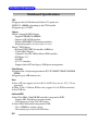
MS-6763 M-ATX Mainboard Mainboard Specifications CPU h Supports Intel® P4 Northwood (Socket 478) processors. h FSB 533~800MHz, depending on the CPU installed. h Supports up to 3.2GHz. Chipset h Intel® Springdale-PE/G chipset - Supports FSB 800/533/400MHz. - Supports AGP 8X/4X interface. - Supports DDR 400/333/266 memory interface. - Integrated graphics (for Springdale-G only). h Intel® ICH5 chipset - Hi-Speed USB (USB2.0) controller, 480Mb/sec. - 2 Serial ATA/150 ports.
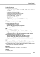
Getting Started On-Board Peripherals h On-Board Peripherals include: - 1 floppy port supports 2 FDDs with 360K, 720K, 1.2M, 1.44M and 2.88Mbytes - 2 serial ports (COM A & JCOM1) - 1 parallel port supports SPP/EPP/ECP mode - 1 VGA port (for 865GM3 Series only) - 8 USB 2.0 ports (Rear * 4/ Front * 4) - 1 Line-In/Line-Out/Mic-In port - 1 RJ45 LAN jack - 2 IEEE 1394 ports (optional for 865PEM2 Series only) Audio h AC97 link controller integrated in ICH5. h Software audio codec AD1981B.
MS-6763 M-ATX Mainboard Mainboard Layout JCOM1 FDD1 Winbond 83627HF-AW T: Mouse B: Keyboard ATX1 CPU_FAN JPW1 Intel 865PE T: Line-In M: Line-Out B: Mic IDE 1 IDE 2 DIMM 4 DIMM 2 PCI Slot 1 DIMM 3 DIMM 1 AGP Slot BATT + SYS_FAN JSP1 RealTek RTL8101L JCD1 PCI Slot 2 ICH5 NEC D72874GC PCI Slot 3 JAUX1 JAUD1 JUSB1 JMD1 J1394_1 JBAT1 JCI1 Codec CNR SATA2 SATA1 JUSB2 BIOS JFP1 865PEM2 Series (MS-6763 v1.
Getting Started JCOM1 FDD1 Winbond 83627HF-AW T: Mouse B: Keyboard ATX1 CPU_FAN JPW1 Intel 865G T: Line-In M: Line-Out B: Mic IDE 1 IDE 2 DIMM 3 PCI Slot 1 DIMM 4 DIMM 1 Intel 82547EI DIMM 2 AGP Slot BATT + SYS_FAN JSP1 PCI Slot 2 ICH5 JCD1 PCI Slot 3 JAUX1 JAUD1 JUSB1 JMD1 JBAT1 JCI1 Codec CNR SATA2 SATA1 JUSB2 BIOS JFP1 865GM3 Series (MS-6763 v1.
Hardware Setup Chapter 2. Hardware Setup Hardware Setup This chapter provides you with the information about hardware setup procedures. While doing the installation, be careful in holding the components and follow the installation procedures. For some components, if you install in the wrong orientation, the components will not work properly. Use a grounded wrist strap before handling computer components. Static electricity may damage the components.
MS-6763 M-ATX Mainboard Quick Components Guide DDR DIMMs, p.2-7 CPU_FAN, p.2-19 CPU, p.2-3 JCOM1, p.2-11 ATX1, p.2-9 FDD1, p.2-16 Back Panel I/O, p.2-10 JPW1, p.2-9 IDE2/1, p.2-17 AGP1, p.2-26 SYS_FAN, p.2-19 SATA2/1, p.2-18 JBAT1, p.2-25 JCI1, p.2-16 JSP1, p.2-20 JCD1, p.2-20 JFP1, p.2-21 CNR1, p.2-26 JMD1, p.2-20 PCI 1~3, p.2-26 J1394_1, p.2-24 JUSB1/2, p.2-23 2-2 JAUX1, p.2-20 JAUD1, p.
Hardware Setup Central Processing Unit: CPU The mainboard supports Intel® Pentium® 4 processors in the 478 pin package. The mainboard uses a CPU socket called PGA478 for easy CPU installation. When you are installing the CPU, make sure the CPU has a heat sink and a cooling fan attached on the top to prevent overheating. If you do not find the heat sink and cooling fan, contact your dealer to purchase and install them before turning on the computer.
MS-6763 M-ATX Mainboard CPU Installation Procedures for Socket 478 1. Please turn off the power and unplug the power cord before installing the CPU. 2. Pull the lever sideways away from the socket. Make sure to raise the lever up to a 90-degree angle. 3. Look for the gold arrow. The gold arrow should point towards the lever pivot. The CPU can only fit in the correct orientation. 4. If the CPU is correctly installed, the pins should be completely embedded into the socket and can not be seen.
Hardware Setup Installing the CPU Fan As processor technology pushes to faster speeds and higher performance, thermal management becomes increasingly important. To dissipate heat, you need to attach the CPU cooling fan and heatsink on top of the CPU. Follow the instructions below to install the Heatsink/Fan: 1. Locate the CPU and its retention mechanism on the motherboard. 2. Position the heatsink onto the retention mechanism. retention mechanism 3. Mount the fan on top of the heatsink.
MS-6763 M-ATX Mainboard 5. Connect the fan power cable from the mounted fan to the 3-pin fan power connector on the board.
Hardware Setup Memory The mainboard provides four 184-pin unbuffered PC3200/PC2700/ PC2100 DDR DIMMs and supports the memory size up to 4GB. To operate properly, at least two DIMM modules must be installed onboard. DDR DIMM Slots (DIMM 1~4) Memory Speed/CPU FSB Support Matrix DDR200 DDR266 DDR333 DDR400 FSB400 V V X X FSB533 V V V X FSB800 V V V V DDR Population Rules Install at least one DIMM module on the slots. Each DIMM slot supports up to a maximum size of 1GB.
MS-6763 M-ATX Mainboard Please refer to the following table for detailed dual-channel DDR population rules. Other combination not listed below will function as singlechannel DDR.
Hardware Setup Power Supply The mainboard supports ATX power supply for the power system. Before inserting the power supply connector, always make sure that all components are installed properly to ensure that no damage will be caused. ATX 20-Pin Power Connector: ATX1 This connector allows you to connect to an ATX power supply. To connect to the ATX power supply, make sure the plug of the power supply is inserted in the proper orientation and the pins are aligned.
MS-6763 M-ATX Mainboard Back Panel The back panel provides the following connectors: 1394 Port Mouse Keyboard USB Ports LAN Parallel (for 865PEM2) VGA Port COM A L-In (Optional) USB Ports L-Out Mic-In (for 865GM3) Mouse/Keyboard Connector The mainboard provides a standard PS/2® mouse/keyboard mini DIN connector for attaching a PS/2® mouse/keyboard. You can plug a PS/2® mouse/ keyboard directly into this connector.
Hardware Setup Serial Port Connectors: COMA & JCOM1 The mainboard offers two 9-pin serial ports COMA and JCOM1. All ports are 16550A high speed communication ports that send/receive 16 bytes FIFOs. You can attach a serial mouse or other serial device directly to them.
MS-6763 M-ATX Mainboard Parallel Port Connector: LPT1 The mainboard provides a 25-pin female centronic connector as LPT. A parallel port is a standard printer port that supports Enhanced Parallel Port (EPP) and Extended Capabilities Parallel Port (ECP) mode.
Hardware Setup LAN Jack: 10/100Mbps LAN (for 865PEM2 Series) or Gigabit LAN (for 865GM3 Series) The mainboard provides one standard RJ-45 jack for connection to Local Area Network (LAN). Two LAN chipsets are available upon request: 1. 10/100Mbps LAN for 865PEM2-IL mainboard. 2. Gigabit LAN for 865GM3-F mainboard. Gigabit LAN enables data to be transferred at 1000, 100 or 10Mbps. 10/ 100 LAN enables data to be transferred at 100 or 10Mbps. You can connect a network cable to this LAN jack.
MS-6763 M-ATX Mainboard IEEE1394 Port (Optional for 865PEM2 Series only) The back panel provides one standard IEEE 1394 port. The standard IEEE1394 port connects to IEEE1394 devices without external power. The IEEE1394 high-speed serial bus complements USB by providing enhanced PC connectivity for a wide range of devices, including consumer electronics audio/video (A/V) appliances, storage peripherals, other PCs, and portable devices.
Hardware Setup Audio Port Connectors Line Out is a connector for Speakers or Headphones. Line In is used for external CD player, Tape player, or other audio devices. Mic is a connector for microphones.
MS-6763 M-ATX Mainboard Connectors The mainboard provides connectors to connect to FDD, IDE HDD, case, audio, LAN, USB Ports, and CPU/System fans. Floppy Disk Drive Connector: FDD1 The mainboard provides a standard floppy disk drive connector that supports 360K, 720K, 1.2M, 1.44M and 2.88M floppy disk types. FDD1 Chassis Intrusion Switch Connector: JCI1 (Optional) This connector is connected to 2-pin connector chassis switch. If the chassis is open, the switch will be short.
Hardware Setup Ultra ATA HDD Connectors: IDE1, IDE2 The mainboard has a 32-bit Enhanced PCI IDE and Ultra DMA 33/66/ 100 controller that provides PIO mode 0~4, Bus Master, and Ultra DMA 33/ 66/100 function. You can connect up to four hard disk drives, CD-ROM, 120MB Floppy (reserved for future BIOS) and other devices. These connectors support the provided IDE hard disk cable. IDE2 IDE1 IDE1 (Primary IDE Connector) The first hard drive should always be connected to IDE1.
MS-6763 M-ATX Mainboard Serial ATA HDD Connectors: SATA1, SATA2 The mainboard provides dual high-speed Serial ATA interface ports. The ports support 1st generation Serial ATA data rates of 150MB/s and are fully compliant with Serial ATA 1.0 specifications. Each Serial ATA connector can connect to 1 hard disk drive.
Hardware Setup Fan Power Connectors: CPU_FAN/SYS_FAN The CPU_FAN (processor fan) and SYS_FAN (system fan) support system cooling fan with +12V. It supports three-pin head connector. When connecting the wire to the connectors, always take note that the red wire is the positive and should be connected to the +12V, the black wire is Ground and should be connected to GND. GND +12V Sensor CPU_FAN GND +12V SENSOR SYS_FAN MSI Reminds You... Always consult the vendors for proper CPU cooling fan.
MS-6763 M-ATX Mainboard CD-In Connector: JCD1 The connector is for CD-ROM audio connector. Modem-In Connector: JMD1 (Optional) The connector is for modem with internal audio connector. Aux Line-In Connector: JAUX1 (Optional) The connector is for DVD add-on card with Line-in connector. SPDIF-Out Connector: JSP1 (Optional) This connector is used to connect SPDIF (Sony & Philips Digital Interconnect Format) interface for digital audio transmission.
Hardware Setup Front Panel Connectors: JFP1 The mainboard provides one front panel connector for electrical connection to the front panel switches and LEDs. The JFP1 is compliant with Intel® Front Panel I/O Connectivity Design Guide.
MS-6763 M-ATX Mainboard Front Panel Audio Connector: JAUD1 The JAUD1 front panel audio connector allows you to connect to the front panel audio and is compliant with Intel® Front Panel I/O Connectivity Design Guide.
Hardware Setup Front USB Connectors: JUSB1, JUSB2 The mainboard provides two USB 2.0 pin headers JUSB1/2 that are compliant with Intel® I/O Connectivity Design Guide. USB 2.0 technology increases data transfer rate up to a maximum throughput of 480Mbps, which is 40 times faster than USB 1.1, and is ideal for connecting high-speed USB interface peripherals such as USB HDD, digital cameras, MP3 players, printers, modems and the like.
MS-6763 M-ATX Mainboard IEEE 1394 Connector: J1394_1 (Optional for 865PEM2 Series) The mainboard provides one 1394 pin header that allows you to connect IEEE 1394 ports via an external IEEE1394 bracket (optional).
Hardware Setup Jumpers The motherboard provides the following jumpers for you to set the computer’s function. This section will explain how to change your motherboard’s function through the use of jumpers. Clear CMOS Jumper: JBAT1 There is a CMOS RAM on board that has a power supply from external battery to keep the data of system configuration. With the CMOS RAM, the system can automatically boot OS every time it is turned on.
MS-6763 M-ATX Mainboard Slots The motherboard provides one AGP slot, three 32-bit PCI bus slots, and one CNR slot. AGP Slot PCI Slots CNR Slot AGP (Accelerated Graphics Port) Slot The AGP slot allows you to insert the AGP graphics card. AGP is an interface specification designed for the throughput demands of 3D graphics. It introduces a 66MHz, 32-bit channel for the graphics controller to directly access main memory. The slot supports 8x/4x cards at 0.8V (AGP 3.0) or 4x cards at 1.5V (3.
Hardware Setup PCI Interrupt Request Routing The IRQ, acronym of interrupt request line and pronounced I-R-Q, are hardware lines over which devices can send interrupt signals to the microprocessor.
BIOS Setup Chapter 3. BIOS Setup BIOS Setup This chapter provides information on the BIOS Setup program and allows you to configure the system for optimum use. You may need to run the Setup program when: An error message appears on the screen during the system booting up, and requests you to run SETUP. You want to change the default settings for customized features.
MS-6763 M-ATX Mainboard Entering Setup Power on the computer and the system will start POST (Power On Self Test) process. When the message below appears on the screen, press key to enter Setup. Press DEL to enter SETUP If the message disappears before you respond and you still wish to enter Setup, restart the system by turning it OFF and On or pressing the RESET button. You may also restart the system by simultaneously pressing , , and keys.
BIOS Setup Getting Help After entering the Setup menu, the first menu you will see is the Main Menu. Main Menu The main menu lists the setup functions you can make changes to. You can use the arrow keys ( ↑↓ ) to select the item. The on-line description of the highlighted setup function is displayed at the bottom of the screen. Sub-Menu If you find a right pointer symbol (as shown in the right view) appears to the left of certain fields that means a sub-menu can be launched from this field.
MS-6763 M-ATX Mainboard The Main Menu Once you enter Award BIOS CMOS Setup Utility, the Main Menu will appear on the screen. The Main Menu displays twelve configurable functions and two exit choices. Use arrow keys to move among the items and press to enter the sub-menu. Standard CMOS Features Use this menu for basic system configurations, such as time, date etc. Advanced BIOS Features Use this menu to configure the special enhanced features.
BIOS Setup PNP/PCI Configurations This entry appears if your system supports PnP/PCI. PC Health Status This menu shows the status of your CPU, fan, overall system status, etc. Monitor function is available only if there is hardware monitoring mechanism onboard. Frequency/Voltage Control Use this menu to specify your settings for frequency/voltage control. Load Default Setting Use this menu to load the BIOS default values that are factory settings for optimal system operations.
MS-6763 M-ATX Mainboard Standard CMOS Features The items inside Standard CMOS Features menu are divided into 10 categories. Each category includes none, one or more setup items. Use the arrow keys to highlight the item you want to modify and use the or keys to switch to the value you prefer. Date (mm:dd:yy) This allows you to set the system to the date that you want (usually the current date). The format is . day Day of the week, from Sun to Sat, determined by BIOS.
BIOS Setup will not work properly if you enter improper information for this category. If your hard disk drive type is not matched or listed, you can use Manual to define your own drive type manually. If you select Manual, related information is asked to be entered to the following items. Enter the information directly from the keyboard. This information should be provided in the documentation from your hard disk vendor or the system manufacturer.
MS-6763 M-ATX Mainboard Advanced BIOS Features Hard Disk Boot Priority This setting determines the boot priority of the installed hard disk drives. Virus Warning The item is to set the Virus Warning feature for IDE Hard Disk boot sector protection. If the function is enabled and any attempt to write data into this area is made, BIOS will display a warning message on screen and beep. Setting options: Disabled, Enabled.
BIOS Setup crease number of users a platform can support, improve reaction and response time, and increase number of transaction that can be executed. Setting options: Enabled, Disabled. MSI Reminds You...
MS-6763 M-ATX Mainboard USB-HDD LAN Disabled The system will boot from the HDD at USB ports. The system will boot from the Network drive. Disable this sequence. Boot Other Device Setting the option to Enabled allows the system to try to boot from other devices if the system fails to boot from the 1st/2nd/3rd boot device. Swap Floppy Drive Setting to Enabled will swap floppy drives A: and B:. Boot Up Floppy Seek Setting to Enabled will make BIOS seek floppy drive A: before booting the system.
BIOS Setup Security Option This specifies the type of BIOS password protection that is implemented. Settings are described below: Option Setup Description The password prompt appears only when end users try to run Setup. System A password prompt appears every time when the computer is powered on or when end users try to run Setup. APIC Mode This field is used to enable or disable the APIC (Advanced Programmable Interrupt Controller).
MS-6763 M-ATX Mainboard Advanced Chipset Features MSI Reminds You... Change these settings only if you are familiar with the chipset. DRAM Timing Selectable Selects whether DRAM timing is controlled by the SPD (Serial Presence Detect) EEPROM on the DRAM module. Setting to By SPD enables DRAM timings to be determined by BIOS based on the configurations on the SPD. Selecting Manual allows users to configure the DRAM timings manually.
BIOS Setup the CAS and RAS strobe signals, used when DRAM is written to, read from or refreshed. Fast speed offers faster performance while slow speed offers more stable performance. Settings: 4, 3, 2 (clocks). DRAM RAS# Precharge This item controls the number of cycles for Row Address Strobe (RAS) to be allowed to precharge. If insufficient time is allowed for the RAS to accumulate its charge before DRAM refresh, refresh may be incomplete and DRAM may fail to retain data.
MS-6763 M-ATX Mainboard AGP Aperture Size (MB) This setting controls just how much system RAM can be allocated to AGP for video purposes. The aperture is a portion of the PCI memory address range dedicated to graphics memory address space. Host cycles that hit the aperture range are forwarded to the AGP without any translation. The option allows the selection of an aperture size of 4, 8, 16, 32, 64, 128, and 256. Init Display First This item specifies which VGA card is your primary graphics adapter.
BIOS Setup Integrated Peripherals OnChip IDE Device Press to enter the sub-menu and the following screen appears: IDE HDD Block Mode Block mode is also called block transfer, multiple commands, or multiple sector read/write. If your IDE hard drive supports block mode (most new drives do), select [Enabled] for automatic detection of the optimal number of block read/write per sector the drive can support. Setting options: Disabled, Enabled.
MS-6763 M-ATX Mainboard IDE DMA Transfer Access This setting is used to enable or disable the DMA transfer function of IDE hard drives under certain operating systems that do not support IDE drivers, ex: DOS. Setting options: Enabled, Disabled. On-Chip Primary/Secondary PCI IDE The integrated peripheral controller contains an IDE interface with support for two IDE channels. Choose Enabled to activate each channel separately.
BIOS Setup Serial ATA Port 1/2 Mode When On-Chip Serial ATA is set to Legacy Mode, setting options will show as follows: 1. Primary Master => Serial ATA Port 1/2 will be set to Primary Master. 2. Primary Slave => Serial ATA Port 1/2 will be set to Primary Slave. 3. Secondary Master => Serial ATA Port 1/2 will be set to Secondary Master. 4. Secondary Slave => Serial ATA Port 1/2 will be set to Secondary Slave. When On-Chip Serial ATA is set to Native Mode, setting options will show as follows: 1.
MS-6763 M-ATX Mainboard For 865PE CSA LAN (Gigabit-LAN) (for 865G) This setting is used to enable/disable the onboard Gigabit LAN controller. Setting options: Disabled, Enabled. USB Controller This setting is used to enable/disable the onboard USB 1.1 controller. Setting options: Disabled, Enabled. USB 2.0 Controller This setting is used to enable/disable the onboard USB 2.0 controller. This setting works only when the operating system installed supports USB 2.0 driver, such as Windows 2000/XP/ME.
BIOS Setup AC97 Modem Auto allows the mainboard to detect whether a modem is used. If a modem is detected, the onboard AC’97 modem controller will be enabled; if not, it is disabled. Disable the controller if you want to use other controller cards to connect a modem. Settings: Auto, Disabled. Onboard LAN Device (for 865PE) This setting is used to enable/disable the onboard 10/100Mbps LAN controller. Setting options: Disabled, Enabled.
MS-6763 M-ATX Mainboard Onboard Parallel Port There is a built-in parallel port on the on-board Super I/O chipset that provides Standard, ECP, and EPP features.
BIOS Setup Power Management Setup MSI Reminds You... S3-related functions described in this section are available only when your BIOS supports S3 sleep mode. ACPI Suspend Type This item specifies the power saving modes for ACPI function. If your operating system supports ACPI, such as Windows 98SE, Windows ME and Windows 2000, you can choose to enter the Standby mode in S1(POS) or S3 (STR) fashion through the setting of this field. Options are: S1 (POS) The S1 sleep mode is a low power state.
MS-6763 M-ATX Mainboard Run VGABIOS if S3 Resume Selecting [Enabled] allows BIOS to call VGABIOS to initialize the VGA card when system wakes up (resumes) from S3 sleep state. The system resume time is shortened when you disable the function, but system will need an AGP driver to initialize the VGA card. Therefore, if the AGP driver of the card does not support the initialization feature, the display may work abnormally or not function after resuming form S3.
BIOS Setup Suspend Mode If system activity is not detected for the length of time specified in this field, all devices except CPU will be shut off. Settings are Disabled, 1 Min, 2 Min, 4 Min, 8 Min, 12 Min, 20 Min, 30 Min, 40 Min and 1 Hour. HDD Power Down If HDD activity is not detected for the length of time specified in this field, the hard disk drive will be powered down while all other devices remain active. Settings: Disabled, 1 through 15 Min.
MS-6763 M-ATX Mainboard MSI Reminds You... If you have changed this setting, you must let the system boot up until it enters the operating system, before this function will work. **Reload Global Timer Events** Primary/Secondary IDE 0/1, FDC/COM/LPT Port, PCI PIRQ [A-D]# Global Timer Events are I/O events whose occurrence can prevent the system from entering a power saving mode or can awaken the system from such a mode.
BIOS Setup PNP/PCI Configurations This section describes configuring the PCI bus system and PnP (Plug & Play) feature. PCI, or Peripheral Component Interconnect, is a system which allows I/O devices to operate at speeds nearing the speed the CPU itself uses when communicating with its special components. This section covers some very technical items and it is strongly recommended that only experienced users should make any changes to the default settings.
MS-6763 M-ATX Mainboard all of the boot and Plug and Play compatible devices. However, this capability means absolutely nothing unless you are using a Plug and Play operating system such as Windows® 95/98. If you set this field to “manual” choose specific resources by going into each of the sub menu that follows this field (a sub menu is preceded by a “¾”). Setting options: Auto (ESCD), Manual. IRQ Resources The items are adjustable only when Resources Controlled By is set to Manual.
BIOS Setup PC Health Status This section shows the status of your CPU, fan, overall system status, etc. Monitor function is available only if there is hardware monitoring mechanism onboard. Chassis Intrusion Detect The field enables or disables the feature of recording the chassis intrusion status and issuing a warning message if the chassis is once opened. To clear the warning message, set the field to Reset. The setting of the field will automatically return to Enabled later.
MS-6763 M-ATX Mainboard Warning Beep This setting allows you to monitor the operation of the CPU fan. Setting to Enabled will activate the warning beep once the system detects the malfunction/halt of the CPU fan.
BIOS Setup Frequency/Voltage Control Use this menu to specify your settings for frequency/voltage control. Auto Detect PCI Clk This item is used to auto detect the PCI slots. When set to Enabled, the system will remove (turn off) clocks from empty PCI slots to minimize the electromagnetic interference (EMI). Setting options: Enabled, Disabled. Spread Spectrum When the motherboard’s clock generator pulses, the extreme values (spikes) of the pulses creates EMI (Electromagnetic Interference).
MS-6763 M-ATX Mainboard Load Default Setting The Default Setting is the default values set by the mainboard manufacturer specifically for optimal performance of the mainboard. When you select Load Default Setting, a message as below appears: Pressing Y loads the default factory settings for optimal system performance.
BIOS Setup Set Supervisor/User Password When you select this function, a message as below will appear on the screen: Type the password, up to six characters in length, and press . The password typed now will replace any previously set password from CMOS memory. You will be prompted to confirm the password. Retype the password and press . You may also press to abort the selection and not enter a password.