G31M3 Series MS-7528 (V1.X) Mainboard G52-75281X4 i PDF 檔案使用 "pdfFactory" 試用版本建立 www.ahasoft.com.
Copyright Notice T he material in this doc ument is the intellec tual property of M ICRO-STAR INTERNATIONAL. We take every care in the preparation of this document, but no guarantee is given as to the correctness of its contents. Our products are under continual improvement and we reserve the right to make changes without notice. Trademarks All trademarks are the properties of their respective owners.
Safety Instructions 1. Always read the safety instructions carefully. 2. Keep this User’s Manual for future reference. 3. Keep this equipment away from humidity. 4. Lay this equipment on a reliable flat surface before setting it up. 5. The openings on the enclosure are for air convection hence protects the equipment from overheating. DO NOT COVER THE OPENINGS. 6. Make sure the voltage of the power source and adjust properly 110/220V before connecting the equipment to the power inlet. 7.
FCC-B Radio Frequency Interference Statement T h is eq uip men t h as been tested and found to c omply with the limits for a Class B digital device, pursuant to Part 15 of the FCC Rules. These limits are designed to provide reasonable protection against harmful interference in a residential installation. This equipment generates, uses and can radiate radio frequency energy and, if not installed and used in accordance with the instructions, may cause harmful interference to radio communications.
WEEE (Waste Electrical and Electronic Equipment) Statement v PDF 檔案使用 "pdfFactory" 試用版本建立 www.ahasoft.com.
vi PDF 檔案使用 "pdfFactory" 試用版本建立 www.ahasoft.com.
vii PDF 檔案使用 "pdfFactory" 試用版本建立 www.ahasoft.com.
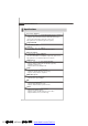
CONTENTS Copyright Notice ......................................................................................................... ii Tradema rks .................................................................................................................. ii Revision History ......................................................................................................... ii Technical Support ......................................................................................................
English G31M3 User’s Guide English En-1 PDF 檔案使用 "pdfFactory" 試用版本建立 www.ahasoft.com.
M S-7528 M ainboard Specifications Processor Support - Intel ® Core™2 Duo/ Core™2 Quad/Pentium Dual-Core E2XXX and Celeron 400 LGA775 processors in LGA775 package. - Supports 4 pin CPU Fan Pin-Header with Fan Speed Control. (For the latest information about CPU, please visit http://global.msi.com.tw/index.
English Floppy - 1 floppy port - Supports 1 FDD with 360KB, 720KB, 1.2MB, 1.44MB and 2.88MB Connectors Back panel - 1 PS/2 m ouse port - 1 PS/2 keyboard port - 1 serial port (COM1) - 1 VGA port - 1 parallel port supporting SPP/EPP/ECP mode - 4 USB 2.0 Ports - 1 RJ-45 LAN Jack - 1 1394 port (optional) - 6 flexible audio jacks/ 3 flexible audio jacks (optional) On-Board Pinheaders/ Connectors - 2 USB 2.
M S-7528 M ainboard 1394 Parallel Port, LAN, Port, p.En-16 p.En-16 p.En-17 (Optional) L-In RS-Out L-Out CS-Out Mic SS-Out Mouse/ Keyboard, Serial Port, VGA Port, p.En-16 p.En-17 p.En-17 JPW1, p.En-14 Audio, p.En-17 JSPD1, p.En-12 JTPM1, p.En-14 SYSFAN1, p.En-9 USB ports, p.En-16 CPU, p.En-5 CPUFAN1, p.En-9 Memory, p.En-7 ATX1, p.En-14 IDE1, p.En-9 PCIE, SYSFAN2, p.En-9 JFP2, BATT + p.En-15 p.En-10 JCI1, p.En-11 SATA1~4, PCI, p.En-15 JFP1, p.En-10 p.
The m ainboard supports Intel ® processor. The mainboard uses a CPU socket called Socket 775 for easy CPU installation. If you do not have the CPU cooler, consult your dealer before turning on the com puter. For the latest information about CPU, please visit http://global.m si.com.tw/index.php? func=cpuform Important Overheating Overheating will seriously damage the CPU and system. Always make sure the cooling fan can work properly to protect the CPU from overheating.
M S-7528 M ainboard CPU & Cooler Installation Procedures for Socket 775 1. The CPU socket has a plastic cap on it to protect the contact from damage. Before you have installed the CPU, always cover it to protect the socket pin. 2. Remove the cap from lever hinge side. 3. The pins of socket reveal. 4. Open the load lever. 5. Lift the load lever up and open the load plate. 6. After confirming the CPU direction for correct mating, put down the CPU in the socket housing frame.
English Memory DDR2 Specification : 240-pin, 1.8v. Single channel definition : All DIMM slots are GREEN color. Dual channels definition : DIMM slot(s) on Channel A are marked in GREEN color. DIMM slot(s) on Channel B are m arked in Orange color. 64x2=128 pin 56x2=112 pin Important - DDR2 memory modules are not interchangeable with DDR and the DDR2 stan dard is not backwards compatible. You should always install DDR2 memory modules in the DDR2 DIMM slots.
M S-7528 M ainboard Volt Notch En-8 PDF 檔案使用 "pdfFactory" 試用版本建立 www.ahasoft.com.
Fan Power Connectors The fan power connectors support system cooling fan with +12V. The CPU FAN supports Smart FAN function. When connect the wire to the connectors, always take note that the red wire is the positive and should be connected to the +12V, the black wire is Ground and should be connected to GND. If the m ainboard has a System Hardware Monitor chipset on-board, you must use a specially designed fan with speed sensor to take advantage of the fan control.
M S-7528 M ainboard Serial ATA Connector This connector is a high-speed Serial ATA interface port. Each connector can connect to one Serial ATA device. Important Please do not fold the Serial ATA cable into 90-degree angle. Otherwise, data loss may occur during transmission. Front Panel Connectors These connectors are for electrical connection to the front panel switches and LEDs. The JFP1 is compliant with Intel ® Front Panel I/O Connectivity Design Guide.
VCC USB1USB1+ GND USBOC This connector, com pliant with Intel ® I/O Connectivity Design Guide, is ideal for connecting high-speed USB interface peripherals such as USB HDD, digital cameras, MP3 players, printers, modems and the like. USB 2.0 Bracket (Optional) 10 9 VCC USB0USB0+ GND Key (no pin) 2 1 Important Note that the pins of VCC and GND must be connected correctly to avoid possible damage. Chassis Intrusion Connector This connector connects to the chassis intrusion switch cable.
M S-7528 M ainboard CD-In Connector This connector is provided for external audio input. L GND R S/PDIF-Out Connector or S/PDIF-In Connector This connector is used to connect S/PDIF (Sony & Philips Digital Interconnect Format) interface for digital audio transm ission.
There is a CMOS RAM onboard that has a power supply from an external battery to keep the data of system configuration. W ith the CMOS RAM, the system can automatically boot OS every time it is turned on. If you want to clear the system configuration, set the jumper to clear data. 1 1 Keep Data (default) 1 Clear Data Important You can clear CMOS by shorting 2-3 pin while the system is off. Then return to 12 pin position. Avoid clearing the CMOS while the system is on; it will damage the mainboard.
M S-7528 M ainboard Power Supply Attachment Before inserting the power supply connector, always make sure that all components are installed properly to ensure that no dam age will be caused. All power connectors on the mainbnoard have to connect to the ATX power supply and have to work together to ensure stable operation of the mainboard. ATX 24-Pin Power Connector This connector allows you to connect an ATX 24-pin power supply.
English PCI (Peripheral Component Interconnect) Express Slot The PCI Express slot supports the PCI Express interface expansion card. The PCI Express x 16 supports up to 4.0 GB/s transfer rate. The PCI Express x 1 supports up to 250 MB/s transfer rate.
M S-7528 M ainboard Back Panel Mouse/Keyboard The standard PS/2® mouse/keyboard DIN connector is for a PS/2® mouse/keyboard. PS/2 Mouse connector (Green/ 6-pin female) PS/2 Keyboard connector (Purple/ 6-pin female) 1394 Port The IEEE1394 port on the back panel provides connection to IEEE1394 devices. LAN The standard RJ-45 LAN jack is for connection to the Local Area Network (LAN). You can connect a network cable to it.
A parallel port is a standard printer port that supports Enhanced Parallel Port (EPP) and Extended Capabilities Parallel Port (ECP) m ode. 13 1 (25-pin female connector) 25 14 Serial Port The serial port is a 16550A high speed comm unications port that sends/ receives 16 bytes FIFOs. You can attach a serial m ouse or other serial devices directly to the connector. 1 5 (9-Pin Male Connector) 6 9 VGA Port The DB15-pin female connector is provided for monitor.
M S-7528 M ainboard BIOS Setup This chapter provides basic information on the BIOS Setup program and allows you to configure the system for optimum use. You may need to run the Setup program when: * An error message appears on the screen during the system booting up, and requests you to run BIOS SETUP. * You want to change the default settings for customized features. Important 1.The items under each BIOS category described in this chapter are under continuous update for better system performance.
Power on the computer and the system will start POST (Power On Self Test) process. W hen the m essage below appears on the screen, press key to enter Setup. Press DEL to enter SETUP If the message disappears before you respond and you still wish to enter Setup, restart the system by turning it OFF and On or pressing the RESET button. You may also restart the system by simultaneously pressing , , and keys.
M S-7528 M ainboard The Main Menu Once you enter AMI ® or AW ARD® BIOS CMOS Setup Utility, the Main Menu will appear on the screen. The Main Menu allows you to select from ten setup functions and two exit choices. Use arrow keys to select among the items and press to accept or enter the sub-menu. Standard CMOS Features Use this menu for basic system configurations, such as time, date etc. Advanced BIOS Features Use this menu to setup the item s of special enhanced features.
1. Load Optimized Defaults : Use control keys (↑↓ ) to highlight the Load Optimized Defaults field and press , a message as below appears: Press [Ok] to load the default settings for optimal system performance. 2. Setup Date/ Time : Select the Standard CMOS Features and press to enter the Standard CMOS Features-m enu. Adjust the Date, Tim e fields. 3.
M S-7528 M ainboard Software Information Take out the Driver/Utility CD that is included in the mainboard package, and place it into the CD-ROM driver. The installation will auto-run, sim ply click the driver or utiltiy and follow the pop-up screen to com plete the installation. The Driver/Utility CD contains the: Driver menu - The Driver menu shows the available drivers. Install the driver by your desire and to activate the device.
Benutzerhandbuch Deutsch D-1 PDF 檔案使用 "pdfFactory" 試用版本建立 www.ahasoft.com.
M S-7528 M ainboard Spezifikationen Pro z es sor en - Intel ® Core™2 Duo/ Core™2 Quad/Pentium Dual-Core E2XXX und Celeron 400 LGA775 Prozessoren für Sockel LGA775. - Unterstützt CPU Lüftersteuerung über 4 Stiftleisten. (W eitere CPU Inform ationen finden Sie unter http://global.msi.com.tw/index.php?func=cpuform) FSB (Front-Side-Bus) - 800/1066/1333 MHz Chipsatz - North-Bridge: Intel ® G31 Chipsatz - South-Bridge: Intel ® ICH7/ ICH7R(optional) Chipsatz Speicher - DDR2 667/800 SDRAM (max.
Di sk et te - 1 Disketten Anschluss - Unterstützt 1 Diskettenlaufwerk mit 360KB, 720KB, 1.2MB, 1.44MB und 2.88MB Anschlüsse Deutsch Hintere Ein-/ und Ausgänge - 1 PS/2 Mausanschluss - 1 PS/2 Tastaturanschluss - 1 Serielle Anschluss (COM1) - 1 VGA Anschluss - 1 Parallele Schnittstelle, unterstützt die Betriebsmodi SPP/EPP/ ECP - 4 USB 2.0 Anschlüsse - 1 RJ-45 LAN Anschluss - 1 1394 Anschluss (optional) - 6 Audiobuchsen/ 3 Audiobuchsen (optional) On-Board Stiftleiste/ Anschlüsse - 2 USB 2.
M S-7528 M ainboard Parallele Schnittstelle, S.D-17 1394 LAN, Port, S.D-16 S.D-16 (Optional) L-In RS-Out L-Out CS-Out Mic SS-Out Ma us -/ Serielle VGA USB ports, Schnittstelle, Anschluss, S.D-16 S.D-17 S.D-17 Tastatur, S.D-16 JPW1, S.D-14 S.D-17 JSPD1, S.D-12 JTPM1, S.D-14 SYSFAN1, S.D-9 Audio, CPU, S.D-5 CPUFAN1, S.D-9 Speicher, S.D-7 ATX1, S.D-14 IDE1, S.D-9 PCIE, SYSFAN2, S.D-9 JFP2, BATT + S.D-15 S.D-10 JCI1, S.D-11 SATA1~4, PCI, S.D-15 JFP1, S.D-10 S.
Hauptprozessor: CPU Das Mainboard unterstützt Intel ® Prozessoren und verwendet hierfür einen CPU Sockel mit der Bezeichnung Sockel-775, um das Einsetzen der CPU zu erleichtern. Verfügen Sie über keinen Kühler, setzen Sie sich bitte mit Ihrem Händler in Verbindung, um einen solchen zu erwerben und danach zu installieren, bevor Sie Ihren Com puter anschalten. Deutsch Um die neuesten Informationen zu unterstützten Prozessoren zu erhalten, besuchen Sie bitte http://global.msi.com.tw/index.
M S-7528 M ainboard CPU & Kühler Einbau für Sockel 775 1. Der CPU-Sockel besitzt zum Schutz eine Plastikabdeckung. Lassen Sie vor der Installtion diese Schutzkappe auf dem Sockel um Schäden zu verm eiden. 2. Entfernen Sie zuerst die Schutzkappe wie abgebildet in Pfeilrichtung. 3. Sie sehen jetzt die Pins des Sockels. 4. Öffnen Sie den Sockelverschlusshebel. 5. K l a p p e n S i e d en H e b e l g an z a u f u n d ö f f n en S i e d i e Metallverschlussklappe. 6.
Speicher DDR2 Spezifikation : 240-Pin, 1.8v. Single Channel : Um das Mainboard in Single Channel zu betreiben, nutzen Sie bitte die GRÜN gefärbten DIMM Bänke. 64x2=128 Pin Deutsch Dual Channel : Um das Mainboard in Dual Channel zu betreiben,nutzen Sie bitte die GRÜN gefäbten (Kanal A) und ORANGE gefäbten DIMM Bänke (Kanal B) parallel.
M S-7528 M ainboard Volt Notch D-8 PDF 檔案使用 "pdfFactory" 試用版本建立 www.ahasoft.com.
Anschlüsse, Steckbrücken und Slots Stromanschlüsse für Lüfter Die Anschlüsseunterstützen aktive Systemlüfter mit + 12V. CPU FAN kann Smart FAN Funktion unterstützen. Wenn Sie den Anschluss herstellen, sollten Sie im mer darauf achten, dass der rote Draht der positive Pol ist, und mit +12V verbunden werden sollte, der schwarze Draht ist der Erdkontakt und sollte mit GND verbunden werden.
M S-7528 M ainboard Serial ATA Anschluss Der Anschluss ist ein Hochgeschwindigkeits Serielle-ATA Interface. Pro Anschluss kann ein S-ATA Gerät angeschlossen werden. Wichtig Bitte falten Sie das Serial ATA Kabel nicht in einem Winkel von 90 Grad, da dies zu Datenverlusten während der Datenübertragung führt . Frontpanel Anschlüsse Diese Anschlüsse sind für das Frontpanel dienen zum Anschluss der Schalter und LEDs des Frontpaneels.
USB Vorderanschluss (Gelb) VCC USB1USB1+ GND USBOC Dieser Anschluss entspricht den Richtlinien des Intel ® I/O Connectivity Design Guide, ist bestens geeignet, Hochgeschwindigkeits- USB- Peripheriegeräte anzuschließen, wie z. B. USB Festplattenlaufwerke, Digitalkameras, MP3-Player, Drucker, Modems und ähnliches. USB 2.
M S-7528 M ainboard CD- Eingang Dieser Anschluss wird für externen Audioeingang zur Verfügung gestellt . L GND R S/PDIF- Ein-/ SPDIF- Ausgang Dieser Anschluss dienen zum Anschluss einer SPDIF (Sony & Philips Digital Interconnect Format) Schnittstelle zur digitalen Übertragung von Audiodaten.
Steckbrücke zur CMOS- Löschung Auf dem Mainboard gibt es einen sogenannten CMOS Speicher (RAM), der über eine Batterie gespeist wird und die Daten der Systemkonfiguration enthält. Er ermöglicht es dem Betriebssystem, m it jedem Einschalten automatisch hochzufahren. W ollen Sie die Systemkonfiguration löschen, verwenden Sie hierfür JBAT1 (Clear CMOS Jum per Steckbrücke zur CMOS Löschung).
M S-7528 M ainboard Zusätzlicher Hinweis Stromversorgung Bevor Sie eine Verbindung m it den Strom anschlüssen herstellen, stellen Sie im mer sicher, dass alle Komponenten ordnungsgem äß eingebaut sind, um jegliche Schäden auszuschließen. Alle Stromanschlüsse auf dem Mainboard müssen mit einem ATX Netzteil verbunden werden und müssen gemeinsam den stabilen Betrieb des Mainboards sicher stellen. ATX 24-Pin Stromanschluss Hier können S ie ei n ATX 24-P in Netztei l anschließen.
PCI (Peripheral Component Interconnect) Express Slot Der PCI Express Slot unterstützt die PCI Express Schnittstelle Erweiterungskarten. Der PCI Express x 16 Slot unterstützt die Datenubertragunsraten von bis zu 4.0 GB/s. Der PCI Express x 1 Slot unterstützt die Datenubertragunsraten von bis zu 250 MB/s.
M S-7528 M ainboard Hinteres Anschlusspanel Maus-/Tastatur Die Standard PS/2® Maus/Tastatur Stecker Mini DIN ist für eine PS/2® Maus/Tastatur. PS/2 Mausanschluss (Grün/ 6-Pin Buchse) PS/2 Tastaturanschluss (Lila/ 6-Pin Buchse) 1394 Port Das IEEE 1394 Port auf der hintere Anschlusspanel zu den Vorrichtungen IEEE1394. LAN Die Standard RJ-45 Buchse ist für Anschlus zum an ein Lokales Netzwerk (Local Area Network - LAN). Hier kann ein Netzwerkkabel angeschlossen werden.
Parallele Schnittstelle Die Parallele Schnittstelle ist eine Standard Druckerschnittstelle, die ebenso als Enhanced Parallel Port (EPP) und als Extended Capabilities Parallel Port (ECP) betrieben werden kann. 13 1 (25-Pin Centronics Anschlussbuchse) 14 Serielle Schnittstelle Bei der Seriellen Schnittstelle handelt es sich um eine 16550A Hochgeschwindigkeitskommunikationsschnittstelle, die 16 Bytes FIFOs sendet/empfängt.
M S-7528 M ainboard BIOS Setup Dieses Kapitel enthält Informationen über das BIOS Setup und ermöglicht es Ihnen, Ihr System optim al auf Ihre Anforderungen einzustellen. Notwendigkeit zum Aufruf des BIOS besteht, wenn: * W ährend des Bootvorgangs des Systems eine Fehlerm eldung erscheint und Sie zum Aufruf des BIOS SETUP aufgefordert werden. * Sie die W erkseinstellungen zugunsten individueller Einstellungen ändern wollen. Wichtig 1.
Aufruf des BIOS Setups Nach dem Einsc halten beginnt der Com puter den POST (P ower On Self Test Selbstüberprüfung nach Anschalten). Sobald die Meldung unten erscheint, drücken Sie die Taste () um das Setup aufzurufen. Press DEL to enter SETUP Deutsch W enn die Nachricht verschwindet, bevor Sie reagieren und Sie möchten imm er noch ins Setup, starten Sie das System neu, indem Sie es erst AUS- und danach wieder ANSCHALTEN, oder die “RESET”-Taste am Gehäuse betätigen.
M S-7528 M ainboard Das Hauptmenü Nachdem Sie das AMI ® oder AWARD ® BIOS CMOS Setup Utility, aufgerufen haben, erscheint das Hauptmenü. Es weist zehn Setup- Funktionen und zwei Arten das Menü zu verlassen auf. Verwenden Sie die Pfeiltasten, um im Menü zu navigieren und drücken Sie die Eingabetaste (), um ein Unterm enü aufzurufen. Standard CMOS Features In diesem Menü können Sie die Basiskonfiguration Ihres Systems anpassen, so z.B. Uhrzeit, Datum usw.
W enn hereinkommen Sie, gründen das BIOS Dienstprogramm, folgen Sie den Prozessen unten für allgem einen Gebrauch. W ählen Sie [Ok] und drücken Einter, um die Standard Einstellungen für ein optimales System zu laden. 2. Einstellung Datum/ Zeit : W ählen Sie die “Standard-CMOS Eigenschaften” vor und betätigen Sie um das Standard-CMOS Eigenschaft -Menü einzutragen. Justieren Sie das Datum, Zeit fängt auf. 3. Außer u. Ausgang Einstellung : Die Gebrauchsteuerschlussel (↑↓ ), zum der Außer u.
M S-7528 M ainboard Software-Informationen Nehmen Sie den Treiber herausGebrauchs-CD, die im mainboard Paket eingeschlossen ist, und setzen Sie es in den CD-ROM Treiber. Die Installation wird Autom obil-laufen lassen, klicken Sie einfach den Treiber oder utiltiy und folgen Sie dem pop-up Schirm, um die Installation durchzuführen. Der TreiberGebrauchs-CD enthält: Treibermenü - das Treibermenü zeigt die vorhandenen Treiber. Bringen Sie den Treiber durch Ihren Wunsch und die Vorrichtung zu aktivieren an.
Installation Matériel G31M3 Français Guide d’Utilisation Français Fr-1 PDF 檔案使用 "pdfFactory" 試用版本建立 www.ahasoft.com.
La Carte M ère MS-7528 Spécificités Processeurs Supportés - Intel ® Core™2 Duo/ Core™2 Quad/Pentium Dual-Core E2XXX et Celeron 400 LGA775 Processeurs de socket LGA775 - Supporte un connecteur de 4 pins du ventilateur de CPU avec le Contrôleur de la vitesse du ventilateur (Pour plus d’informations, veuillez visiter http://global.msi.com.tw/ index.
Installation Matériel Disquette - 1 port de disquette - Supporte 1 FDD avec 360KB, 720KB, 1.2MB, 1.44MB et 2.88MB Connecteurs Français Panneau arrière - 1 port souris PS/2 - 1 port clavier PS/2 - 1 port sérial (COM1) - 1 port VGA - 1 port parallèle qui supporte le m ode SPP/EPP/ECP - 4 ports USB 2.0 - 1 jack LAN RJ-45 - 1 port IEEE 1394 (optionnel) - 6 jacks audio flexibles/ 3 jacks audio flexibles (optionnel) Connecteurs intégrés - 2 connecteurs USB 2.
La Carte M ère MS-7528 Port Port Parallèle, LAN, 1394, p.Fr-16 p.Fr-16 p.Fr-17 (Optional) L-In RS-Out L-Out CS-Out Mic SS-Out Souris/ Clavier, Port Série, Port VGA, Port USB, Audio, p.Fr-16 p.Fr-17 p.Fr-17 p.Fr-16 p.Fr-17 JSPD1, p.Fr-12 JTPM1, p.Fr-14 SYSFAN1, p.Fr-9 JPW1, p.Fr-14 CPU, p.Fr-5 CPUFAN1, p.Fr-9 Memory, p.Fr-7 ATX1, p.Fr-14 IDE1, p.Fr-9 PCIE, SYSFAN2, p.Fr-9 JFP2, BATT + p.Fr-15 p.Fr-10 JCI1, p.Fr-11 SATA1~4, PCI, p.Fr-15 JFP1, p.Fr-10 p.
Installation Matériel Central Processing Unit: CPU La carte mère supporte le processeur Intel ®. Elle utilise un Socket-775 pour l’installation. Si vous ne possédez pas de systèm e de refroidissem ent du CPU, contactez votre revendeur pour vous en procurer un et installet le avant d’allumer l’ordinateur. Pour pl us d’inform ations, veuill ez c onsulter: ht tp:/ /global. m si. com .tw/ index.
La Carte M ère MS-7528 Procédure d’installation du CPU pour Socket 775: 1. La douille du CPU porte un chapeau en plastique pour la protéger des contacts qui lui causeraient des dom mages. Avant d’installé le CPU, couvrez-le pour protéger la goupille de la douille. 2. Enlevez le chapeau du côté du levier. 3. Les goupilles de la douille se m ontent. 4. Ouvrez le levier effectif. 5. Soulevez le levier effectif et ouvrez le plat effectif. 6.
Installation Matériel Mémoire DDR2 Spécification : 240-pin, 1.8v. Définition du canal : Tous les slots DIMM sont Verts. Définition de canaux double: Slot(s) DIMM sur le canal A est en Vert. Slot(s) DIMM sur le canal B est en Orange . 64x2=128 pin 56x2=112 pin - Les modules DDR2 ne sont pas interchangeables avec la DDR et le standard DDR2 n’est pas compatible en arrière, vous devez toujours installer le module de la mémoire DDR2 dans la fente de DDR2 DIMM et la DDR dans la fente de DDR DIMM.
La Carte M ère MS-7528 Volt Entaille Fr-8 PDF 檔案使用 "pdfFactory" 試用版本建立 www.ahasoft.com.
Installation Matériel Connecteurs, Cavaliers, Slots Connecteurs Alimentation du Ventilateur: Les connecteurs au système du ventilateur supportent la puissance du ventilateur avec +12V. Le CPUFAN1 du CPU supporte la fonctione Smart FAN. Quand vous reliez le fil aux connecteurs, notez que le fil rouge est positif et doit être relié au +12V, le fil noir est rectifié et mis à terre.
La Carte M ère MS-7528 Connecteur Série ATA Le connecteur SATA supporte le port Serial ATA de hautes performances. Chaque connecteur de SATA peut se connecter à un disque dur. Important Veuillez ne pas tordre le câble Série ATA à90 degrés, cela entraînera la perte de données lors des phases de transfert. Connecteurs panneau en façade La carte mère possède deux connecteurs pour la connexion électrique du panneau avant (LED, switch).
Installation Matériel Connecteur USB en façade (Jaune) VCC USB1USB1+ GND USBOC Ce connecteur est com patible avec IntelR I/O Connectivity Design Guide, il est idéal pour la connexion de matériels possédant une interface USB tel que: disque dur USB, caméra digitale, imprimante, lecteur MP3 et bien d’autres périphériques. USB 2.
La Carte M ère MS-7528 Connecteur CD-Entrée Ces connecteurs perm ettent l’audio input externe.. L GND R Le connecteur de sortie S/PDIF ou entrée S/PDIF Ce connecteur est utilisée pour connecter l’interface S/PDIF (Format d’interconnexion numérique Sony et Philips) afin de transm ettre le son audio num érique.
Installation Matériel Cavalier Effacer CMOS Le CMOS RAM intégré reçoit une alimentation garder les données de configuration du système. autom atiquem ent dém arrer avec les paramètres que le PC est allum é. Si vous voulez effacer la cavalier pour effacer les données.
La Carte M ère MS-7528 Attachement d’Alimentation d’Énergie: Avant d’insérer le connecteur d’alim entation d’énergie, assurez-vous toujours que tous les composants sont installés correctement afin de ne pas causer de dommage. Tous les connecteurs de puissance sur la carte mère doivent se relier à l’alimentation d’énergie d’ATX et doivent travailler ensem ble pour une opération stable. Connecteur Alimentation ATX-24 Broches Ce connecteur vous permet de connecter l’alimentation ATX 24-pin.
Installation Matériel Slot PCI Express (x16/ x4/ x1) Le slot PCI Express supporte la carte d'extension de l'interface PCI Express. Le PCI Express x 16 supporte un taux de transfert jusqu'a 4.0 GB/s. Le PCI Express x 1 supporte un taux de transfert jusqu'a 250 MB/s. Slots PCI Express x16 bleu foncé supportent la vitesse de PCI Express x 16 (PCI_E1) Slot de PCI (Interconnexion Composante Périphérique) Les slots PCI vous permettent d’insérer des cartes d’extension selon vos besoins.
La Carte M ère MS-7528 Panneau Arrière Connecteur port Souris/ Clavier Le connecteur PS/2 ® souris/clavier DIN est conçu pour brancher un PS/2 ® souris/ clavier. Connecteur PS/2 Souris (Vert / 6-pin féminin) Connecteur PS/2 Clavier(Violet/ 6-pin féminin) Port 1394 Le port 1394 sur le panneau arrière fournit le raccordement pour les dispositifs 1394. LAN Le standard RJ-45 jack est utile pour le raccordem ent au Réseau de Région Local (LAN). Vous pouvez relier un câble de réseau à celui-ci.
Installation Matériel Connecteur Port Parallèle : Un port parallèle est un port d’im prim ante standard qui supporte le port parallèle amélioré (EPP, Frhanced Parallel Port) et le m ode d’ECP(Extended Capabilities Parallel Port) 13 1 (Connecteur 25-pin féminin) 25 14 Connecteur Port Série Le port série est un port de communication 16550A à grande vitesse qui envoie/ reçoit 16 bytes FIFOs. Vous pouvez directement attacher une souris série ou d’autres dispositifs séries au connecteur.
La Carte M ère MS-7528 Configuration du BIOS Ce chapitre vous informe sur le programme d’installation du BIOS et vous perm et de configurer le systèm e pour un usage optim um . Vous pouvez installer le programm e lorsque: * Un message d’erreur apparaît sur l’écran pendant que le système initialise et vous demande de mettre en marche l’INSTALLATION de BIOS. * Vous voulez changer les arrangements par défaut pour des dispositifs adaptés aux besoins du client. Important 1.
Installation Matériel Entrer dans le Setup Allumez votre ordinateur, le système lance le processus de POST (Power On Self Test). Quand le m essage ci-dessous apparaît à l’écran, appuyez sur le bouton pour entrer dans le setup. Press DEL to enter SETUP Si le m essage disparaît avant que vous ne puissiez entrer dans le setup, redémarrez vot re ordi nateur en appuyant sur le bout on RE SE T. Vous pouvez aussi uti li ser sim ultanément la combinaison de touches : , et .
La Carte M ère MS-7528 Menu Principal Une fois entré dans le AMI ® ou AWARD® BIOS CMOS Setup Utility, le menu apparaît à l’écran. Le Menu perm et de sélectionner dix fonctions et deux c hoix de sortie de l’utilitaire. Utilisez les flèches pour vous diriger et utilisez la touche ENTREE pour sélectionner un élément ou entrer dans le sous-menu. Standard CMOS Features Cette fonction perm et le paramétrage des éléments standards du BIOS , comm e les dates, les données etc.
Installation Matériel Une fois que vous êtes entré dans l’installation de BIOS, suivez les processus ci-dessous. 1. Load Optimized Defaults : Utilisez les touches de contrôle( ↑↓ ) pour accentuer le champ de Load Optimized Defaults(Charge Optimisée par Défaut) et la pression < Entrer >, pour obtenir le message suivant: Pressez [ Correct ] pour effectuer les arrangem ents de défaut et pour l’exécution optimale de systèm e. Français 2.
La Carte M ère MS-7528 Information de Logiciel Sortez le pilote/ Service du CD, qui est inclus dans le paquet de la carte mère et placez-le dans le CD-ROM.L’installation va autom atiquement se déclencher, cliquez sur le pilote ou sur l’usage et suivez le pop-up de l’écran pour accomplir l’installation. Le pilote/Service CD contient : Un menu de pilote -Il montre les pilotes disponibles. Installez le pilote si vous le souhaitez pour activer le dispositif.
G31M3 Руководство Русский пользователя Русский Ru-1 PDF 檔案使用 "pdfFactory" 試用版本建立 www.ahasoft.com.
MS-7528 Системная плата Характеристики Процессоры - Intel ® Core™2 Duo/ Core™2 Quad/Pentium Dual-Core E2XXX и Celeron 400 LGA775 процессоры в конструктиве LGA775. - Поддерж к а 4-к он т вен тил я т ора п роц ес с ор а с ф унк ц и ей управления скоростью вращения. (Для получения самой новой информации о CPU, посетите сайт http://global.msi.com.tw/index.
Флоппи - 1 флоппи порт - Поддержка 1 FDD с 360KB, 720KB, 1.2MB, 1.44MB и 2.88MB Коннекторы Русский Задней панели - 1 PS/2 порт мыши - 1 PS/2 порт клавиатуры - 1 последовательный порт (COM1) - 1 порт VGA - 1 параллельный порт поддерживает режимы SPP/EPP/ECP - 4 порта USB 2.0 - 1 разъем RJ-45 LAN - 1 порт 1394 (опционально) - 6 звуковых разъемов с гибким переназначением/ 3 звуковых разъема с гибким переназначением (опционально) Разъемы, установленные на плате - 2 разъема USB 2.
MS-7528 Системная плата Разъем 1394, LAN, параллельного порта, p.Ru-16 p.Ru-16 p.Ru-17 (опционально) L-In RS-Out L-Out CS-Out Mic SS-Out Разъемы мыши/ кливиатуры, COM, VGA, p.Ru-16 p.Ru-17 p.Ru-17 JPW1, p.Ru-14 Аудио разъемы, p.Ru-16 p.Ru-17 JSPD1, p.Ru-12 JTPM1, p.Ru-14 SYSFAN1, p.Ru-9 USB, CPU, p.Ru-5 CPUFAN1, p.Ru-9 Память, p.Ru-7 ATX1, p.Ru-14 IDE1, p.Ru-9 PCIE, SYSFAN2, p.Ru-9 JFP2, BATT + p.Ru-15 p.Ru-10 JCI1, p.Ru-11 SATA1~4, PCI, p.Ru-15 JFP1, p.Ru-10 p.
Центральный процессор: CPU Эта с ис темная п лата п оддерж ивает проц ес с оры от I ntel ®. Для облегчения установки процессора на ней установлен разъем под названием Socket 775. Если у вас нет процес сорного кулера, пожалуйста, свяж итесь с дилером с целью приобретения и его установки до того, как включите компьютер. Самую последнюю информацию о CPU можно получить на сайте http://global.msi. com .tw/index.php?func=cpuform Внимание Перегрев Перегрев может серьезно повредить центральный процессор и систему.
MS-7528 Системная плата Установка процессора и вентилятора для Socket 775 1. Р азъем п роц ес сора зак рыт п лас тик овой к рышк ой, которая защищает контакты разъема от повреждений. При отсутствии процессора, необходимо всегда закрывать разъем пластиковой крышкой для защиты его контактов. 2. Снимите крышку, подняв ее с одной стороны. 3. Откроются контакты разъема. 4. Потяните за рычаг крепления. 5. Поднимите рычаг и отк ройте металлическ ую к рышк у для установки процес сора. 6.
Память DDR2 Спецификация: 240-конт, 1.8v. Один канал памяти: все слоты DIMM зеленого цвета. Два канала памяти: слоты DIMM канала A зеленого цвета, слоты DIMM канала B оранжевого цвета. 64x2=128 конт 56x2=112 конт Внимание - Для работы в двухканальном режиме убедитесь, что в разъемах разных каналов у вас установлены модули одного типа и одинаковой ёмкости. - Чтобы система загрузилась, в начале установите модули в разъемы DIMM1.
MS-7528 Системная плата Volt Notch Ru-8 PDF 檔案使用 "pdfFactory" 試用版本建立 www.ahasoft.com.
Коннекторы, перемычки, разъемы Разъемы питания вентиляторов Разъемы питания вентиляторов поддерживают вентиляторы с питанием +12В. Вентилятор процессора поддерживает функцию Smart FAN. При подключении необходимо помнить, что красный провод подключается к линии +12В, черный- к земле GND.Е сли на системной п лате установлена микрос хема ап паратного мониторинга, необходимо использовать специальные вентиляторы с датчиками скорости для реализации функции управления вентиляторами.
MS-7528 Системная плата Разъем Serial ATA Данный разъем является высокоскоростным портом интерфейса Serial ATA. Любой разъем Serial ATA может соединяться с одним устройством Serial ATA. Внимание Избегайте, пожалуйста, резких изгибов кабеля Serial ATA. В противном случае могут возникнуть потери данных при передаче. Коннекторы передней панели Эт и к оннек т ор ы ис п ол ьз уют с я д ля п одк лю чен ия к ноп ок и и нди к аторов, располож енных на передней панели корпуса.
Выносные порты USB (Желтый коннектор) VCC USB1USB1+ GND USBOC Разъем, соответс твует спец ификации I ntel ® I/O Connectivity Design, идеально подходит для подключения таких высокоскоростных периферийных устройств, как USB HDD, цифровые камеры, MP3 плееры, принтеры и им подобные. USB 2.0 Bracket (опционально) 10 9 VCC USB0USB0+ GND Key (no pin) 2 1 Помните, что во избежание повреждений, контакты VCC и GND должны быть правильно подключены.
MS-7528 Системная плата Коннектор CD-In Этот коннектор предназначен для подключения внешного входа аудио. L GND R Коннектор входа/ выхода S/PDIF Этот разъем используется для подключения интерфейса S/PDIF (Sony & Philips Digital Interconnect Format) для передачи звука в цифровом формате.
Перемычка сброса CMOS На плате установлена CMOS память с питанием от батарейки, хранящая данные о к онфигурац ии с ис темы. Данные, хранящ иеся в CMOS п амяти, требуютс я компьютеру для загрузки операционной системы при вк лючении. Если у вас возникает необходимость сбросить конфигурацию системы (очистить CMOS), воспользуйтесь этой перемычкой. 1 1 Keep Data (default) 1 Clear Data Очистка CMOS производится соединением контактов 2-3 при отключенной системе.
MS-7528 Системная плата Подключение источника питания Перед подключением разъема питания, во избежание повреждений обязательно убедитесь, что все компоненты установлены правильно. Все разъемы питания должны быть подключены к блоку питаня ATX для обеспечения стабильной работы системной платы. 24-контактный разъем питания ATX Этот разъем позволяет подключить 24-контактный коннектор блока питания ATX. Перед подключением источника питания убедитесь, что его разъем и контакты правильно сориентированы.
Слот PCI (Peripheral Component Interconnect) Express Слот PCI Express поддерживает карты расширения интерфейса PCI Express. Слот PCI Express x 16 поддерживает скорость передачи данных до 4.0 ГБ/с. Слот PCI Express x 1 поддерживает скорость передачи данных до 250 МБ/с.
MS-7528 Системная плата Задняя панель Разъемы мыши/клавиатуры Ст ан дартн ые р азъем ы DI N P S / 2 ® д ля п одк лю чения м ыш и / к лавиату ры с интерфейсом PS/2 ®. Разъем PS/2 для мыши (6-контактнаый, зеленый Разъем PS/2 для клавиатуры (6-контактный, фиолетовый) Порт 1394 Порт IEEE1394 на задней панели позволяет подключать устройства IEEE1394. LAN Стандартный разъем RJ-45 для подключения к локальной вычислительной сети (LAN). К нему подключается кабель локальной сети. Цвет LED Лев. Оранж.
Разъем параллельного порта Параллельный порт - это стандартный порт для принтера. Он поддерживает режимы EPP (усовершенствованный параллельный порт) и ECP (параллельный порт с дополнительными возможностями). 13 1 (25-контактная розетка Сentronic) 25 14 Разъем последовательного порта Это высокоскоростной последовательный порт связи 16550A с 16-битной передачи F I F O. К э том у разъем у м ож но н еп ос л ед с т венн о п од к л юч и ть м ыш ь дл я последовательного порта или другие устройство.
MS-7528 Системная плата Настройка BIOS В этой главе приводятся основные сведения о режиме настройки BIOS (BIOS SETUP), который позволяет установить оптимальлную конфигурацию системы. Этот режим может потребоваться в следующих случаях: * Во время загрузки системы появляется сообщение об ошибке с требованием запустить BIOS SETUP. * Вы желаете заменить заводские настройки на собственные. Внимание 1.
Вход в режим настройки Вк лючите п итание компьютера. При этом запуститс я п роц едура POST (Тест включения питания). Когда на экране появится приведенное ниже сообщение, нажмите клавишу для входа в режим настройки. Press DEL to enter SETUP Если сообщение исчезло, а вы не успели нажать клавишу, перезапустите систему, выключив и снова включив питание, или нажать кнопку RESET. Можно, также, перезапустить систему, нажав одновременно клавиши , , и .
MS-7528 Системная плата Main Menu (Главное меню) При входе в режим настройки BIOS от AMI ® или AWARD® на экране отображается Главное меню. Главное меню позволяет выбрать десять функций настройки и имеет два варианта выхода. Для перемещения по пунктам используются клавиши со стрелками и для подтверждения или входа в подменю. Standard CMOS Features (Стандартные функции CMOS) Это меню позволяет установить ос новные параметры конфигурации системы (дату, время, и т.д.
В общем случае, находясь в режиме настройки BIOS, рекомендуется выполнить следующие действия. 1. Load Optimized Defaults : Клавишами управления ( ↑↓ ) выберите пункт Load Optimized Defaults и нажмите , появится следующее сообщение: Нажмите [Ok], чтобы загрузить настройки по умолчанию для оптимальной производительности системы. 3.
MS-7528 Системная плата Сведения о программном обеспечении Установите в CD привод диск Driver/Utility (Драйверы и утилиты) из комплекта поставк и сис темной п латы. А втоматическ и зап ус тится инсталляция. Прос то нажмите на название драйвера/ утилиты и следуйте инструкциям на экране для завершения инсталяции. Диск Driver/Utility содержит: Driver m enu (Меню драйверов) - Из имеющихся драйверов выберите нужный для активации устройства.