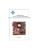
K8NGM2 Series MS-7207 (v2.
FCC-B Radio Frequency Interference Statement This equipment has been tested and found to comply with the limits for a class B digital device, pursuant to part 15 of the FCC rules. These limits are designed to provide reasonable protection against harmful interference in a residential installation. This equipment generates, uses and can radiate radio frequency energy and, if not installed and used in accordance with the instruction manual, may cause harmful interference to radio communications.
This device complies with Part 15 of the FCC Rules. Operation is subject to the following two conditions: (1) this device may not cause harmful interference, and (2) this device must accept any interference received, including interference that may cause undesired operation Copyright Notice T he material in this document is the intellec tual property of M ICRO-STAR INTERNATIONAL. W e take every care in the preparation of this document, but no guarantee is given as to the correctness of its contents.
Technical Support If a problem arises with your system and no solution can be obtained from the user’s manual, please contact your place of purchase or local distributor. Alternatively, please try the following help resources for further guidance. † Visit the MSI homepage & FAQ site for technical guide, BIOS updates, driver updates, and other information: http://www.msi.com.tw & http://www.msi. com.tw/program/service/faq/faq/esc_faq_list.php † Contact our technical staff at: http://support.msi.com.
WEEE Statement v
vi
vii
CONTENTS FCC-B Radio Frequency Interference Statement .......................................................... ii Copyright Notice .............................................................................................................. iii Technical Support .......................................................................................................... iv Safety Instructions .........................................................................................................
Chassis Intrusion Switch Connector: JCI1 .............................................. 2-18 SPDIF-Out/ SPDIF-In Connector: JSPDO1/JSPDI1 (SPDIF-In is optional) 2-19 Audio-out Connector: J1 ........................................................................... 2-19 Serial Port Header: JCOM1 (Optional) ..................................................... 2-20 IEEE 1394 Connectors: J1394_1 (Optional) ............................................ 2-20 Front Panel Connector: JFP1/JFP2 .....................
Access Point Mode ..................................................................................... 4-7 WLAN Card Mode ........................................................................................ 4-8 Live Update .......................................................................................................... 4-9 MEGA STICK ....................................................................................................... 4-10 Basic Function ......................................
Mixer ............................................................................................................. A-8 AudioIO ....................................................................................................... A-12 S/PDIF ......................................................................................................... A-15 Microphone ................................................................................................ A-17 3D Audio Demo ..............................
Getting Started Ch ap ter 1 . Get ti ng Started Getting Started Thank you for choosing the K8NGM2 Series (MS-7207 v2.X) Micro ATX mainboard. The K8NGM2 Series mainboards are based on nVidia® GeForce 6150/6100 & nVidia® nForce 430/410 chipsets for optimal system efficiency. Designed to fit the advanced AMD® K8 Athlon 64 FX processor, the K8NGM2 Series deliver a high performance and professional desktop platform solution.
MS-7207 M-ATX Mainboard Mainboard Specifications CPU † Supports 64-bit AMD ® K8 Athlon64/ Athlon64FX processor (Socket 939). † Supports 4800+ and higher CPU. (For the latest information about CPU, please visit http://www.msi.com.tw/program/products/mainboard/mbd/pro_mbd_cpu_support.php) Chipset † nVidia® GeForce 6150/6100 Chipset (Optional) - HyperTransportTM connection to AMD K8 Athlon64 processor. - 8 or 16 bit control/address/data transfer both directions.
Getting Started MSI Reminds You... 1. Please note that users cannot install OS, either WinME or Win98, in their SATA hard drives. Under these two OSs, SATA can only be used as an ordinary storage device. 2. To create a bootable RAID volume for a Windows 2000 environment, Microsoft’s Windows 2000 Service Pack 4 (SP4) is required. As the end user cannot boot without SP4, a combination installation CD must be created before attempting to install the operating system onto the bootable RAID volume.
MS-7207 M-ATX Mainboard † The mainboard provides a Desktop Management Interface (DMI) function which records your mainboard specifications. Dimension † Micro-ATX Form Factor: 24.4cm X 24.4cm M ounting † 8 mounting holes 1394 GUID address Label (optional) MSI Reminds You... 1. E ac h bo ar d w ill b e giv en a uniqu e 1 39 4 G UID f rom t he manufacturer’s default settings in the system BIOS. 2. Use the flash utility or Live Update from MSI’s website for BIOS update.
Getting Started Mainboard Layout K8NGM2 Series (MS-7207 v2.
MS-7207 M-ATX Mainboard Packing Checklist MSI Driver/Utility CD SATA Cable (Optional) Power Cable (Optional) Standard Cable for Floppy Disk Standard Cable for IDE Devices 1394 Bracket (Optional) USB Bracket (Optional) Back IO Shield User’s Guide TV-out Bracket (Optional) Audio-out Bracket (Optional) MSI motherboard * The pictures are for reference only. Your packing contents may vary depending on the model you purchased.
Hardware Setup Chapter 2. Hardware Setup Hardware Setup This chapter tells you how to install the CPU, memory modules, and expansion cards, as well as how to setup the jumpers on the mainboard. Also, it provides the instructions on connecting the peripheral devices, such as the mouse, keyboard, etc. W hile doing the installation, be careful in holding the components and follow the installation procedures.
MS-7207 M-ATX Mainboard Quick Components Guide JTV1, p.2-22 JPW1, p.2-9 CPUFAN1, p.2-15 DDR DIMMs, p.2-7 JCOM1, p.2-20 CPU, p.2-3 Back Panel I/O, p.2-10 JCI1, p.2-18 FDD1, p.2-15 ATX1, p.2-9 SYSFAN1, p.2-15 NBFAN1, p.2-15 IDE1/2, p.2-16 PCI Express Slots, p.2-25 SATA1~4, p.2-17 PCI Slots, p.2-25 JFP2, p.2-21 J1, p.2-19 JCD1, p.2-18 JAUD1, p.2-18 J1394_1, p.2-19 JSPDO1, p.2-19 JSPDI1, p.2-19 2-2 JFP1, p.2-21 JUSB1, JUSB2, p.2-23 SW1, p.
Hardware Setup Central Processing Unit: CPU The mainboard supports AMD ® Athlon64 processor. The mainboard uses a CPU socket called Socket-939 for easy CPU installation. W hen you are installing the CPU, make sure the CPU has a heat sink and a cooling fan attached on the top to prevent overheating. If you do not have the heat sink and cooling fan, contact your dealer to purchase and install them before turning on the computer. For the latest information about CPU, please visit http://www.msi.com.
MS-7207 M-ATX Mainboard CPU Installation Procedures for Socket 939 1. Please turn off the power and unplug the power cord before installing the CPU. Open Lever Sliding Plate 90 degree 2. Pull the lever s ideways away from the socket. Make sure to raise the lever up to a 90-degree angle. Gold arrow 3. Look for the gold arrow of the CPU. The gold arrow should point as shown in the picture. The CPU c an on l y f i t i n t h e c or r ec t orientation. Correc t CP U placement 4.
Hardware Setup Installing AMD Athlon64 CPU Cooler Set W hen you are installing the CPU, make sure the CPU has a heat sink and a cooling fan attached on the top to prevent overheating. If you do not have the heat sink and cooling fan, contact your dealer to purchase and install them before turning on the computer. MSI Reminds You... Mainboard photos shown in this section are for demonstration of the cooler installation for Socket 939 CPUs only.
MS-7207 M-ATX Mainboard 5. Position the cooling set onto the retention mechanism. 7. Fasten down the lever. Hook one end of the clip to hook first, and then press down the other end of the clip to fasten the cooling s et on the top of the retention mechanism. 8. Make sure the safety hook completely clasps the fixed bolt of the retention mechanism. 6. Locate the Fix Lever, Safety Hook and the Fixed Bolt. Lift up the intensive fixed lever. 9.
Hardware Setup Memory The mainboard provides 4 slots for 184-pin DDR DIMM (Double In-Line Memory Module) modules and supports the memory size up to 4GB. You can install DDR 333/ 400 modules on the DDR DIMM slots (DIMM 1~4). DIM M1~DIMM4 (from left to right) DIMM Module Combination Install at least one DIMM module on the slots. Each DIMM slot supports up to a maximum size of 1GB. Users can install either single- or double-sided modules to meet their own needs.
MS-7207 M-ATX Mainboard Installing DDR Modules 1. 2. 3. The DDR DIMM has only one notch on the center of module. The module will only fit in the right orientation. Insert the DIMM memory module vertically into the DIMM slot. Then push it in until the golden finger on the memory module is deeply inserted in the socket. The plastic clip at each side of the DIMM slot will automatically close.
Hardware Setup Power Supply The mainboard supports ATX power supply for the power system. Before inserting the power supply connector, always make sure that all components are installed properly to ensure that no damage will be caused. ATX 24-Pin Power Connector: ATX1 This connector allows you to connect an ATX 24-pin power supply. To connect the ATX 24-pin power supply, make sure the plug of the power pin 13 supply is inserted in the proper orientation and the pins are aligned.
MS-7207 M-ATX Mainboard Back Panel Parallel M ou se DVI Port Keyboard 1394 Port L-In (Optional) LAN VGA Port (for GeForce 6150) (optional) USB Ports USB Ports L-Out Mic Mouse/Keyboard Connector The mainboard provides a standard PS/2® mouse/keyboard mini DIN connector for attaching a PS/2® mouse/keyboard. You can plug a PS/2® mouse/keyboard directly into this connector.
Hardware Setup Digital Panel Connector (for GeForce 6150 only) (optional) The mainboard provides a DVI (Digital Visual Interface) connector which allows you to connect an LCD monitor. The DVI connector provides a high-speed digital interconnection between the computer and its display device. To connect a LCD monitor, simply plug your monitor cable into the DVI connector, and make sure that the other end of the cable is properly connected to your monitor. (refer to your monitor manual for more information.
MS-7207 M-ATX Mainboard LAN (RJ-45) Jack:10/100 LAN (RTL8201CL) or Giga-bit LAN (VSC8201RX : optional) The mainboard provides 1 standard RJ-45 jack for connection to single Local Area Network (LAN). This LAN enables data to be transferred at 10/ 100Mbps or (1000Mbps for VSC8201RX only). You can connect a network cable to it. Activity Indicator Link Indicator 8 1 RJ-45 LAN Jack LED Color LED State Condition Left Orange Off On (steady state) On (brighter & pulsing) LAN link is not established.
Hardware Setup Audio Port Connectors & Audio Header (J1) The 3 audio jacks are for 2-channel mode for stereo speaker output: Line Out is a connector for Speakers or Headphones. Line In is used for external CD player, Tape player, or other audio devices. Mic is a connector for microphones. However, there is an advanced audio application provided by Realtek ALC880 to offer support for 7.1-channel audio operation. You can use the external audio cable and the rear audio connectors to function the 2-/4-/5.1-/7.
MS-7207 M-ATX Mainboard Parallel Port Connector: LPT1 The mainboard provides a 25-pin female centronic connector as LPT. A parallel port is a standard printer port that supports Enhanced Parallel Port (EPP) and Extended Capabilities Parallel Port (ECP) mode.
Hardware Setup Connectors Floppy Disk Drive Connector: FDD1 The mainboard provides a standard floppy disk drive connector that supports 360K, 720K, 1.2M, 1.44M and 2.88M floppy disk types. FDD1 Fan Power Connectors: CPUFAN1/SYSFAN1/NBFAN1 The fan power connectors support system cooling fan with +12V. W hen connecting the wire to the connectors, always take note that the red wire is the positive and should be connected to the +12V, the black wire is Ground and should be connected to GND.
MS-7207 M-ATX Mainboard ATA133 Hard Disk Connectors: IDE1 & IDE2 The mainboard has a 32-bit Enhanced PCI IDE and Ultra DMA 66/100/133 controller that provides PIO mode 0~4, Bus Master, and Ultra DMA 66/100/133 function. You can connect up to four hard disk drives, CD-ROM and other IDE devices. The Ultra ATA133 interface boosts data transfer rates between the computer and the hard drive up to 133 megabytes (MB) per second.
Hardware Setup Serial ATAII Connectors: SATA1~SATA4 (nForce 410 supports 2 SATA only) T he Mainboard s upports f our s erial ATAII c onnec tors SATA1~SATA4. SATA1~SATA4 are high-speed Serial ATAII interface ports. Each supports 2st generation serial ATA data rates of 300MB/s and is fully compliant with Serial ATA 1.0 specifications. Each Serial ATAII connector can connect to 1 hard disk device.
MS-7207 M-ATX Mainboard CD-In Connector: JCD1 This connector is provided for CD-ROM audio. JCD1 R GND L Front Panel Audio Connector: JAUD1 The JAUD1 front panel audio connector allows you to connect to the front panel audio and is compliant with Intel® Front Panel I/O Connectivity Design Guide.
Hardware Setup SPDIF-Out/ SPDIF-In Connector: JSPDO1/ JSPDI1 (SPDIF-In is optional) These connectors are used to connect SPDIF (Sony & Philips Digital Interconnect Format) interface for digital audio transmission. The JSPDO1 is for SPDIF-Out and the JSPDI1 is for SPDIF-In. SPDIF-Out GND GND SPDIF-In NC NC JSPDI1 JSPDO1 Connected to JSPDO1 or JSPDI1 is by your desire.
MS-7207 M-ATX Mainboard Serial Port Header: JCOM1 (Optional) The mainboard offers one 9-pin header as serial port. The port is a 16550A high speed communication port that sends/receives 16 bytes FIFOs. You can attach a serial mouse or other serial device directly to it.
Hardware Setup Front Panel Connector: JFP1/JFP2 The mainboard provides one front panel connector for electrical connection to the front panel switches and LEDs. The JFP1 is compliant with Intel® Front Panel I/O Connectivity Design Guide.
MS-7207 M-ATX Mainboard TV-Out Connector: JTV1 (For GeForce 6150 Only, Optional) The mainboard optionally provides a TV-Out connector for you to attach a TVOut bracket that integrated HDTV-out. The TV-Out bracket offers two types of TVOut connectors: S-Video and RCA Composite connectors. Select the appropriate one to connect to the standard television or the HDTV (High-Definition TeleVision) and it will be able to display PC’s information.
Hardware Setup Front USB Connectors: JUSB1 / JUSB2 The mainboard provides two standard USB 2.0 pin headers JUSB1 & JUSB2 . USB 2.0 technology increases data transfer rate up to a maximum throughput of 480Mbps, which is 40 times faster than USB 1.1, and is ideal for connecting highspeed USB interface peripherals such as USB HDD, digital cameras, MP3 players, printers, modems and the like. JUSB1 & JUSB2 Pin Definition PIN SIGNAL PIN SIGNAL 1 VCC 2 VCC JUSB1, JUSB2 3 USB4- 4 USB5- (USB 2.
MS-7207 M-ATX Mainboard Button The motherboard provides the following button for you to set the computer’s function. This section will explain how to change your motherboard’s function through the usage of the button. Clear CMOS Button: SW1 There is a CMOS RAM on board that has a power supply from external battery to keep the system configuration data. W ith the CMOS RAM, the system can automatically boot OS every time it is turned on.
Hardware Setup Slots The motherboard provides one PCI Express x16 slot, one PCI Express x1 slot, and two 32-bit PCI bus slots. PCI Express Slots The PCI Express slot, as a high-bandwidth, low pin count, serial, interconnect technology. PCI Express architecture provides a high performance I/O infrastructure for Desktop Platforms with transfer rates starting at 2.5 Giga transfers per second over a PCI Express x1 lane for Gigabit Ethernet, TV Tuners, 1394 controllers, and general purpose I/O.
BIOS Setup Chapter 3. BIOS Setup BIOS Setup This chapter provides information on the BIOS Setup program and allows you to configure the system for optimum use. You may need to run the Setup program when: ² An error message appears on the screen during the system booting up, and requests you to run SETUP. ² You want to change the default settings for customized features. MSI Reminds You... 1.
MS-7207 M-ATX Mainboard Entering Setup Power on the computer and the system will start POST (Power On Self Test) process. W hen the message below appears on the screen, press key to enter Setup. Press DEL to enter SET UP If the message disappears before you respond and you still wish to enter Setup, restart the system by turning it OFF and On or pressing the RESET button. You may also restart the system by simultaneously pressing , , and keys.
BIOS Setup Getting Help After entering the Setup menu, the first menu you will see is the Main Menu. M ain M enu The main menu lists the setup functions you can make changes to. You can use the control keys ( ↑↓ ) to select the item. The on-line description of the highlighted setup function is displayed at the bottom of the screen.
MS-7207 M-ATX Mainboard The Main Menu Once you enter AMI® BIOS CMOS Setup Utility, the Main Menu (Figure 1) will appear on the screen. The Main Menu allows you to select from twelve setup functions and two exit choices. Use arrow keys to select among the items and press to accept or enter the sub-menu. Standard CMOS Features Use this menu for basic system configurations, such as time, date etc. Advanced BIOS Features Use this menu to setup the items of AMI® special enhanced features.
BIOS Setup Cell_M enu This menu shows the frequency of CPU. Load Fail-Safe Defaults Use this menu to load the default values set by the BIOS vendor for stable system performance. Load Optimized Defaults Use this menu to load the default values set by the mainboard manufacturer specifically for optimal performance of the mainboard. BIOS Setting Password Use this menu to set the Password. Save & Exit Setup Save changes to CMOS and exit setup. Exit Without Saving Abandon all changes and exit setup.
MS-7207 M-ATX Mainboard Standard CMOS Features The items in Standard CMOS Features Menu are divided into several categories. Each category includes no, one or more than one setup items. Use the arrow keys to highlight the item and then use the or keys to select the value you want in each item. Date (MM:DD:YY) This allows you to set the system to the date that you want (usually the current date). The format is .
BIOS Setup Dev ice This item shows the information about the specified item (Read-only). Type This item defines the HDD parameters. LBA/Large M ode This item allows you to enable or disable the LBA (Logical Block Address, logical block size in hard disk) mode. Setting options: [Auto], [Disabled]. the Block Mode W hen the setting is Auto, it will read or write more sector at every circle to enhance the hard disk performance. Setting options: [Auto], [Disabled].
MS-7207 M-ATX Mainboard Hard Disk S.M.A.R.T. This allows you to activate the S.M.A.R.T. (Self-Monitoring Analysis & Reporting Technology) capability for the hard disks. S.M.A.R.T is a utility that monitors your disk status to predict hard disk failure. This gives you an opportunity to move data from a hard disk that is going to fail to a safe place before the hard disk becomes offline. Settings: [Auto], [Enabled], [Disabled].
BIOS Setup Advanced BIOS Features Quick Boot Select Enabled to reduce the amount of time required to run the power-on self-test (POST). A quick POST skips certain steps. We recommend that you normally disable quick POST. It is better to find a problem during POST than lose data during your work. Setting options: [Enabled], [Disabled]. Full Screen LOGO Display This item enables you to show the company logo on the bootup screen. Settings are: [Enabled] Shows a still image (logo) on the full screen at boot.
MS-7207 M-ATX Mainboard IOAPIC Function This field is used to enable or disable the APIC (Advanced Programmable Interrupt Controller). Due to compliance with PC2001 design guide, the system is able to run in APIC mode. Enabling APIC mode will expand available IRQ resources for the system. Setting options: [Enabled], [Disabled]. M PS Table Version This field allows you to select which MPS (Multi-Processor Specification) version to be used for the operating system.
BIOS Setup Advanced Chipset Features MSI Reminds You... Change these settings only if you are familiar with the chipset. M emclock M ode Users can place an artificial memory clock on the system. Please note that memory is prevented from running faster than this frequency. Setting options:[Auto], [Limit]. M CT Timing M ode This field has the capacity to automatically detect all of the DRAM timing. The settings are: [Auto], [Manual].
MS-7207 M-ATX Mainboard a technique that DRAM itself predicts the address of the next memory location to be accessed after the first address is accessed. To use the feature, you need to define the burst length, which is the actual length of burst plus the starting address and allows internal address counter to properly generate the next memory location. The bigger the size, the faster the DRAM performance. Setting options: [8 Beats], [4 Beats] and [2 Beats].
BIOS Setup TV M ode Support This item allows you to select the TV display mode. Setting options: [NTSC_M], [NTSC_J], [PAL_M], [PAL_BDGHI], [PAL_N], [PAL_NC], [Default]. OnChip VGA Trap Enable Setting options: [Enabled] and [Disabled]. CPU-LDT Frequency, MHz This setting shows the current CPU Front Side Bus clock frequency. PCI-Express Frequency, MHz This setting shows the current PCI-Express Front Side Bus clock frequency.
MS-7207 M-ATX Mainboard Integrated Peripherals USB 1.1 Controller This setting disables/enables the USB 1.1 controller. Setting options: [Enabled], [Disabled]. USB 2.0 Controller Set to [Enabled] if you need to use any USB 2.0 device in the operating system that does not support or have any USB 2.0 driver installed, such as DOS and SCO Unix. Setting options: [Disabled], [Enabled]. USB Device Legacy Support Set to Enabled if your need to use any USB 1.1/2.
BIOS Setup Onboard IEEE1394 Controller This setting allows you to enable/disable the onboard IEEE 1394 controller. Setting options: [Enabled], [Disabled]. AZALIA AUDIO Select Enabled to use the audio capabilities of your system. Setting options: [Auto], [Disabled]. M AC LAN This setting controls the onboard LAN controller. Setting options: [Auto], [Disabled]. MAC LAN Bridge This setting controls the onboard LAN bridge. Setting options: [Enabled], [Disabled].
MS-7207 M-ATX Mainboard IDE Devices Configuration Press to enter the sub-menu and the following screen appears: PCI IDE BusM aster This item allows you to enable/ disable the PCI IDE busmaster. Setting options: [Disabled], [Enabled]. On-Chip IDE Controller The integrated peripheral controller contains an IDE interface with support for two IDE channels. Choose [Both] to activate the two channels. Setting options: [Disabled], [Primary], [Secondary], [Both].
BIOS Setup Power Management Features MSI Reminds You... S3-related functions described in this section are available only when your BIOS supports S3 sleep mode. ACPI Function This item is to activate the ACPI (Advanced Configuration and Power Management Interface) Function. If your operating system is ACPI-aware, such as Windows 98SE/ 2000/ME, select [Enabled]. Setting options: [Enabled] and [Disabled]. ACPI Standby State This item specifies the power saving modes for ACPI function.
MS-7207 M-ATX Mainboard Power Button Function This feature allows users to configure the Power Button function. Settings are: [On/Off] The power button functions as a normal power-on/-off button. [Suspend] W hen you press the power button, the computer enters the suspend/sleep mode, but if the button is pressed for more than four seconds, the computer is turned off. Restore on AC Power Loss This setting specifies whether your system will reboot after a power failure or interrupt occurs.
BIOS Setup PS/2 Device Wakeup from S5 This controls how and whether the PS/2 keyboard is able to power on the system from S5. If you choose [Password], you must type the password to power on the system. The S3 wakeup function can be set up from W indows. Settings: [Disabled], [Enabled]. Specific Key for PowerOn If PS/2 Device Wakeup is set to [Enabled], then you can set a key in the field for the PS/2 keyboard to power on the system.
MS-7207 M-ATX Mainboard PNP/PCI Configurations This section describes configuring the PCI bus system and PnP (Plug & Play) feature. PCI, or Peripheral Component Interconnect, is a system which allows I/O devices to operate at speeds nearing the speed the CPU itself uses when communicating with its special components. This section covers some very technical items and it is strongly recommended that only experienced users should make any changes to the default settings.
BIOS Setup IRQ Resource Setup Press to enter the sub-menu and the following screen appears. IRQ 3/4/5/7/9/10/11/14/15 These items specify the bus where the specified IRQ line is used. The settings determine if BIOS should remove an IRQ from the pool of available IRQs passed to devices that are configurable by the system BIOS. The available IRQ pool is determined by reading the ESCD NVRAM.
MS-7207 M-ATX Mainboard MSI Reminds You... IRQ (Interrupt Request) lines are system resources allocated to I/O devices. When an I/O device needs to gain attention of the operating system, it signals this by causing an IRQ to occur. After receiving the signal, when the operating system is ready, the system will interrupt itself and perform the service required by the I/O device.
BIOS Setup H/W Monitor This section shows the status of your CPU, fan, overall system status, etc. Monitor function is available only if there is hardware monitoring mechanism onboard. Chassis Intrusion The field enables or disables the feature of recording the chassis intrusion status and issuing a warning message if the chassis is once opened. To clear the warning message, set the field to [Reset]. The setting of the field will automatically return to [Enabled] later.
MS-7207 M-ATX Mainboard Cell_Menu The items in Cell Menu includes some important settings of CPU, PCIE, DRAM. MSI Reminds You... Change these settings only if you are familiar with the chipset. Current CPU Clock This field shows the current clocks of CPU. Read-only. Cool’n’Quiet This feature is especially desiged for AMD Athlon processor, which provides a CPU temperature detecting function to prevent your CPU’s from overheading due to the heavy working loading. Setting options: [Disabled], [Enabled].
BIOS Setup Adjust DDR Voltage (V) Adjusting the DDR voltage can increase the DDR speed. Any changes made to this setting may cause a stability issue, so changing the DDR voltage for long-term purpose is NOT recommended. Spread Spectrum Press to enter the sub-menu and the following screen appears: W hen the motherboard’s clock generator pulses, the extreme values (spikes) of the pulses creates EMI (Electromagnetic Interference).
MS-7207 M-ATX Mainboard Load Fail-Safe/Optimized Defaults The two options on the main menu allow users to restore all of the BIOS settings to the default Fail-Safe or Optimized values. The Optimized Defaults are the default values set by the mainboard manufacturer specifically for optimal performance of the mainboard. The Fail-Safe Defaults are the default values set by the BIOS vendor for stable system performance.
BIOS Setup BIOS Setting Password W hen you select this function, a message as below will appear on the screen: Type the password, up to six characters in length, and press . The password typed now will replace any previously set password from CMOS memory. You will be prompted to confirm the password. Retype the password and press . You may also press to abort the selection and not enter a password. To clear a set password, just press when you are prompted to enter the password.
Introduction to DigiCell Chapter 4. Introduction to DigiCell Chapter 4. Introduction to DigiCell Introduction to DigiCell DigiCell, the most useful and powerful utility that MSI has spent much research and efforts to develop, helps users to monitor and configure all the integrated peripherals of the system, such as audio program, power management, MP3 files management and communication / 802.11g W LAN settings.
MS-7207 M-ATX Mainboard M SI Feature Main Before using this utility, it is required to have all the integrated peripherals/cards (LAN card, W ireless LAN card, MegaStick... etc.) and all the necessary drivers (onboard LAN driver, audio driver, CoreCenter, Live Update... etc.) installed correctly. The icon representing each item will be lit up if it is inserted/installed correctly and properly. Otherwise, the icon will remain gray and user is not able to view the functionality/connection of that item.
Introduction to DigiCell Software Access Point In this sub-menu, you can change your connection mode to different ones, and configure the advanced settings for each mode, such as the authentication encryption... etc. Live Update You can take advantage of Live Update to detect and update BIOS and drivers online. PC Alert You can take advantage of PC Alert to monitor the health status of your system. M EGA STICK If you have your MEGA STICK connected to your system, this icon will be lit up.
MS-7207 M-ATX Mainboard M SI Feature H/W Diagnostic In the H/W Diagnostic sub-menu, you can see the information, status and note of each DigiCell. You may double check the connection and installation of the item marked as gray. You may also click on the Mail to MSI button to send your questions or suggestions to MSI’s technical support staff.
Introduction to DigiCell Communication In the Communication sub-menu, you can see the status of all the LAN / W LAN / Bluetooth on the screen if the hardware is installed. The first icon indicates the onboard LAN on your system, the second icon indicates the wireless LAN status, and the third one is the information about the bluetooth on your system. Click on each item for details. This icon indicates the information and connection status of onboard LAN, which is read-only.
MS-7207 M-ATX Mainboard M SI Feature Software Access Point In the Software Access Point sub-menu, you can see the communication status on your system and choose the desired software access point mode by clicking on the desired icon, in which the default settings are configured for your usage. The default software access point mode is set to WLAN Card M ode. For more advanced security settings and channels switching, click on “Setting” button to enter its submenu.
Introduction to DigiCell Access Point Mode Click on “Setting” button of the Access Point Mode and the following screen will display. IP Sharing Click on this icon to enable/disable the IP sharing. The default of this setting is disabled. Disabled. Enabled. Enabling/disabling IP sharing depends on the different situation. For example: 1.
MS-7207 M-ATX Mainboard M SI Feature enable this feature, only PCs with MAC address located in Association Control List can connect to the wireless LAN. M AC Address MAC stands for Media Access Control. A MAC address is the hardware address of a device connected to a network. Security This option allows you to enable/disable the authentication function. Authentication Communicates the key across the network. Open: Shared: Devices must have identical W EP settings to communicate.
Introduction to DigiCell Live Update Click on the Live Update icon in the main menu and the Live Update program will be enabled. The Live Update 3™ is a tool used to detect and update your BIOS/drivers/VGA BIOS/VGA Driver/Utility online so that you don’t need to search for the correct BIOS/driver version throughout the whole Web site. To use the function, you need to install the “MSI Live Update 3” application.
MS-7207 M-ATX Mainboard M SI Feature MEGA STICK In the MEGA STICK sub-menu, you can configure the settings of MSI MEGA STICK and the media files (*.m3u, *.mp3, *.wav, *.cda, *.wma) on your system. Basic Function Here you can edit your own play list with the buttons “load”, “save”, “delete”, “shuttle”, “repeat” & “print”. Load Save Del ete Shuffle Repeat Print 4-10 To load media files or the playlist of mp3 files (*.m3u) on your system or on your MEGA STICK. To save a loaded playlist of mp3 files (*.
Introduction to DigiCell There is also a toolbar for you to execute some basic function, like play, stop, pause, previous/next song, song info and volume adjust. There is also a scroll bar on the top for you to forward/rewind. previous pause next forward/rewind bar stop song’s information play Right-click on the MP3 file and choose “Info”, a MP3 Info dialogue will pop up to show the information of the file, including the title, artist, album, release year and others.
MS-7207 M-ATX Mainboard M SI Feature Non-Unicode programs supported If you are using an operating system in European languages, and you’d like to play the media files in MEGA STICK with East-Asian languages (such as Chinese, Japanese... etc.), it is possible that the file names display incorrectly. However, you can ins tall the Supplemental Language Support provided by Microsoft to solve this problem. You need to have your Microsoft Setup CD prepared in the CD-ROM.
Introduction to DigiCell 3. Then go to the [Advanced] tab and select the language you want to be supported (the language of the filename in the MegaStick) from the dropdown list in the [Language for non-Unicode programs], then click [Apply]. The system will install the necessary components from your Microsoft Setup CD immediately.
MS-7207 M-ATX Mainboard M SI Feature PC Alert Click on the PC Alert icon in the main menu and the PC Alert program will be enabled. PC Alert is just like your PC doctor that can detect and view the PC hardware and system status during real time operation. On the top of the screen it shows the current PC hardware status such as the CPU & system temperatures. On the middle of the screen it shows the current system status includiing the Vcore, 3.3V, +5V and +12V. The under screen shows the current fan speeds.
Introduction to DigiCell Power on Agent In the Power on Agent sub-menu, you can configure setting of power-on, poweroff and restarting status. In the screen below, you can set the date, time, start-up programs respectively for power-on, power-off and restarting. Power On Here are the available settings for Power On function: Date Use the drop-down list to select the date for power-on. T im e Use the arrow keys to select the hour/minute/second for power-on, power-off and restarting.
MS-7207 M-ATX Mainboard M SI Feature Power Off / Restart You may configure the time (in the format hh:mm:ss) for the next power-off / restart. Start With Use the button “+Add” to add the start-up programs as DigiCell is activated next time. For example, you may like to have Outlook activated or a specified website linked when you get to the office every morning.
Introduction to DigiCell Auto Login Since the Power On function allows the system to power on automatically, you may have to enable this Auto Login function in the following situations: 1. If you are using a computer belonging to a domain in office, and you need to enter your user name & password everytime when you boot up your computer. 2. If there are multi users using the same computer and you’d like to power on the computer automatically with one specific user.
nVIDIA RAID Introduction Chapter 6. nVidia RAID Introduction nVidia RAID Introduction NVIDIA brings Redundant Array of Independent Disks (RAID) technology—which is used by the world’s leading businesses—to the common PC desktop. This technology uses multiple drives to either increase total disk space or to offer data protection. For all levels, RAID techniques optimize storage solutions by using multiple disks grouped together and treating them as a s ingle storage resource.
M S-7207 M -ATX M ainboard Introduction System Requirement Operating System Support NVRAID supports the following operating systems: W indows XP W indows 2000 Professional RAID Arrays NVRAID supports the following types of RAID arrays described in this section: RAID 0: RAID 0 defines a disk striping scheme that improves the disk read and write times for many applications. RAID 1: RAID 1 defines techniques for mirroring data. RAID 0+1: RAID 0+1 combines the techniques used in RAID 0 and RAID 1 arrays.
nVIDIA RAID Introduction RAID Configuration Basic Configuration Instructions The following are the basic steps for configuring NVRAID: Non-Bootable RAID Array 1. Choose the hard disks that are to be RAID enabled in the system BIOS. (To enable the nVidia RAID Function in nVidia RAID Setup of Integrated Peripherals in BIOS.) 2. Specify the RAID level, either Mirroring (RAID 1), Striping (RAID 0), Striping and Mirroring (RAID 0+1), RAID 5 or JBOD and create the desired RAID array. 3.
M S-7207 M -ATX M ainboard Understanding the “Define a New Array” Window Use the Define a New Array window to • Select the RAID Mode • Set up the Striping Block • Specify which disks to use for the RAID Array Depending on the platform used, the system can have one or more channels. In a typical system there is usually one controller and multiple channels, and each channel has a slave and a master.
nVIDIA RAID Introduction Using the Define a New Array Window If necessary, press the tab key to move from field to field until the appropriate field is highlighted. • Selecting the RAID Mode By default, this is set to [Mirroring]. To change to a different RAID mode, press the down arrow key until the mode that you want appears in the RAID Mode box—either [Mirroring], [Striping], [RAID5], [Spanning], or [Stripe Mirroring].
M S-7207 M -ATX M ainboard Completing the RAID BIOS Setup 1. After assigning your RAID array disks, press F7. The Clear disk data prompt appears. 2. Press Y if you want to wipe out all the data from the RAID array, otherwise press N. You must choose Yes if the drives were previously used as RAID drives. The Array List window appears, where you can review the RAID arrays that you have set up. 3. Use the arrow keys to select the array that you want to set up, then press Enter.
nVIDIA RAID Introduction Installing the RAID Driver (for bootable RAID Array) 1. After you complete the RAID BIOS setup, boot from the W indows CD, and the W indows Setup program starts. 2. Press F6 and wait for the W indows Setup screen to appear. 3. Specify the NVIDIA drivers: (1) Insert the floppy that has the RAID driver, press S, then press Enter. The W indows Setup screen appears as below: MSI Reminds You... Please follow the instruction below to make an nVIDIA Serial ATA RAID driver for yourself.
M S-7207 M -ATX M ainboard 4. Press Enter to continue with W indows XP Installation. Be sure to leave the floppy disk inserted in the floppy drive until the blue screen portion of W indows XP installation is completed, then take out the floppy. 5. Follow the instructions on how to install W indows XP. After W indows XP is completely installed, it is recommended that you install the the RAID management tool. MSI Reminds You...
nVIDIA RAID Introduction NVIDIA RAID Utility Installation Installing the NVIDIA RAID Software Under Windows (for Non-bootable RAID Array) The existing W indows IDE Parallel ATA driver (as well as the Serial ATA driver if SATA is enabled) must be upgraded to use the NVIDIA IDE Parallel ATA driver (as well as the NV Serial ATA driver if SATA is enabled).
M S-7207 M -ATX M ainboard Initializing and Using the Disk Array The RAID array is now ready to be initialized under W indows. 1. Launch Computer Management by clicking “Start” --> “Settings” --> “Control Panel” then open the “Administrative Tools” folder and double click on “Computer Management”. 2. Click “Disk Management” (under the “Storage” section). The Initialize and Convert Disk W izards appears. 3. Click Next. The Select Disks to Initialize window appears.
nVIDIA RAID Introduction 5. Check the disk in the list if you want to make the array a dynamic disk, then click Next. The Completing the Initialize and Convert Disk Wizard window appears. 6. Click Finish. The “Computer Management” window appears. The actual disks listed will depend on your system, and the unallocated partition is the total combined storage of two hard disks. You must format the unallocated disk space in order to use it. 7. Format the unallocated disk space.
M S-7207 M -ATX M ainboard RAID Drives Management There is an application called NVRAIDMAN which helps you perform the following tasks of nVDIA RAID.
nVIDIA RAID Introduction Setting Up a Spare RAID Disk You can designate a hard drive to be used as a spare drive for a RAID 1, RAID 0+1 or RAID 5 array. The spare drive can take over for a failed disk. NVRAID supports two types of spare drives: • Free Disk A free disk is a disk that is not part of any RAID array, but can be used by any available RAID 1 or RAID 0+1 array that requires a particular disk when one of its disks crashes or becomes unusable.
M S-7207 M -ATX M ainboard Assigning a Dedicated Disk To mark a disk as dedicated, or reserve it for use by a specific array, Step 1: Mark the Disk as a Free Disk 1. Enter the system BIOS setup and make sure that the drive that you want to mark as free is RAID enabled. 2. Boot into W indows and run the NVRAIDMAN program. If the disk is not part of any RAID array, then it will appear under the Free Disk section of the RAID GUI.
nVIDIA RAID Introduction 3. Click Next. The RAID Array Selection page appears. 4. From the Free Disk Selection page, select one of the two free disks available. This would be the disk that will be designated to the mirror array. 5. Click Next. The Completing the NVIDIA Spare Disk Allocation page appears. 6. Click Finish. As shown in figure below, the ST380011A drive is now a dedicated free disk in the mirrored array.
M S-7207 M -ATX M ainboard Removing a Dedicated Disk Once a dedicated disk has been assigned to a particular array, it can be removed at any time. To remove the disk, right click on the dedicated disk and select “Remove Disk...” to remove it. In the previous example, simply right click on the ST380011A drive and select “Remove Disk...”.
nVIDIA RAID Introduction Morphing From One RAID Array to Another In a traditional RAID environment, when a user wants to change the current state of a disk or a current array to a new RAID configuration, the process of reconfiguring the new array involves multiple steps. The user must back up the data, delete the array, re-boot the PC, and then reconfigure the new array. NVIDIA RAID allows the end user to change the current state of the disk or array to another with a one-step process called .Morphing..
M S-7207 M -ATX M ainboard From To New Array Disk Requirements RAID 0 m >= > n n2 Number of RAID 0 disks must be equal to or greater than half the number of RAID 0+1 disks. RAID 1 ** Not a valid combination ** RAID 0+1 m >= n+2 ; where m must be an even number of disks. The new array must include at least two more disks than the original array, and can include any even number of disks beyond that.
nVIDIA RAID Introduction 2 Click Next and the following screen shot will appear: 3 Connect the RAID disk that you want to use with any given RAID array. 4 Click Next and the following screen shot will appear: 5 Click Finish. Initializing a RAID Array Initializing a RAID array erases all the data that is stored on that array, and writes all zeros to the disks.
M S-7207 M -ATX M ainboard 1 From the NVRAIDMAN window, right click on any available free disk and select Create Array as show in Figure below. 2 The Create Array W izard opens. Follow the W izard to create a Mirror array. 3 At the Create Array W izard Welcome screen, click Next. 4 At the RAID Array Selection page, make sure that RAID Mode is set to “Mirroring” and Stripe Size is set to its default value of 64K, then click Next.
nVIDIA RAID Introduction 8 Click OK. The Clearing System Data screen appears again with the Initialize Array check box checked as shown below. 9 Click Next, then click Finish at the Completing the NVIDIA Create Array W izard screen. The NVRAIDMAN windows shows the created RAID array as shown below. The Initialization Process As you can see from the screen shot above, the initialization process has started and it will be completed in a short period of time.
M S-7207 M -ATX M ainboard Rebuilding a RAID Array Rebuilding is the process of restoring data to a hard drive from other drives in the array. This applies only to fault tolerant arrays such as RAID 1, RAID 0+1, as well as a RAID 5. For example, assuming you have a three disk RAID 5 array, and one of the drives fail, then you need the lost data on the newly added drive.
nVIDIA RAID Introduction 4. Click Next. The Disk Selection page appears. 5. Select the drive that you want to rebuild by clicking it from the list, then click Next. The Completing the NVIDIA Rebuild Array page appears. 6. Click Finish. The array rebuilding starts after a few seconds, and a small pop-up message appears towards the bottom right corner of the screen as shown in the figure below. W hen the rebuilding process is finished you will see the pop up box shown in Figure below.
M S-7207 M -ATX M ainboard During the rebuilding process, the NVRAID Management utility screen shows the status under the System Tasks and Details sections. M ore About Rebuilding Arrays • Rebuilding Occurs in the Background The rebuilding process is very slow (it can take up to a day) and occurs in the background so as not to affect the performance of the system. • Rebuilding Applies Only to RAID 1/ RAID 0+1 or RAID 5 Arrays Rebuilding an array works only when using RAID 1 , RAID 0+1, or RAID 5.
nVIDIA RAID Introduction Synchronizing a RAID Array Synchronizing an array will force a rebuild of redundancy or parity. The operation is applicable to any fault tolerant array such as RAID 1, 0+1 and RAID 5.
M S-7207 M -ATX M ainboard Usind Disk Alert The RAID manager application includes a disk alert feature that provides a graphical indication of the status of the hard disks in the system. W hen the RAID manager application detects a failure condition of an attached drive, a pop-up box appears in the clock area of the W indows system tray. Click the popup box to view the manufacturer-provide bitmap image of the system motherboard.
Introduction to Realtek ALC880 Appendix A: Introduction to Realtek ALC880 The mainboard is equipped with Realtek ALC880 chip, which provides support for 8-channel audio output, including 2 Front, 2 Rear, 2 Side, 1 Center and 1 Subwoofer channel. ALC880 allows the board to attach 2, 4, 6 or 8 speakers for better surround sound effect. The section will tell you how to install and use 2-, 4-, 6- or 8-channel audio function on the board.
MS-7207 M-ATX Mainboard Installing the Audio Driver You need to install the driver for Realtek ALC880 codec to function properly before you can get access to 2-, 4-, 6- or 8- channel audio operations. Follow the procedures described below to install the drivers for different operating systems. Installation for Windows 2000/XP For W indows ® 2000, you must install W indows ® 2000 Service Pack4 or later before installing the driver.
Introduction to Realtek ALC880 3. Click Next to install the Realtek High Definition Audio Driver. Clic k he r e 4. Click Finish to restart the system.
MS-7207 M-ATX Mainboard Software Configuration After installing the audio driver, you are able to use the 2-, 4-, 6- or 8- channel audio feature now. Click the audio icon from the system tray at the lower-right corner of the screen to activate the HD Audio Configuration. It is also available to enable the audio driver by clicking the Azalia HD Sound Effect Manager from the Control Panel.
Introduction to Realtek ALC880 Sound Effect Here you can select a sound effect you like from the Environment list. Load EQ Setting Reset EQ Setting EQ Setting On/Off Save Preset Delete EQ Setting You may choose the provided sound effects, and the equalizer will adjust automatically.
MS-7207 M-ATX Mainboard Equalizer Selection Equalizer frees users from default settings; users may create their owned preferred settings by utilizing this tool. 10 bands of equalizer, ranging from 100Hz to 16KHz. Save The settings are saved permanently for future use. Enable / Disable To disable, you can temporarily stop the sound effect without losing the settings. Reset 10 bands of equalizer would go back to the default setting.
Introduction to Realtek ALC880 Frequently Used Equalizer Setting Realtek recognizes the needs that you might have. By leveraging our long experience at audio field, Realtek HD Audio Sound Manager provides you certain optimized equalizer settings that are frequently used for your quick enjoyment. [How to Use It] Other than the buttons “Pop” “Live” “Club” & “Rock” shown on the page, to pull down the arrow in “Others” , you will find more optimized settings available to you.
MS-7207 M-ATX Mainboard Mixer In the Mixer part, you may adjust the volumes of the rear and front panels individually. 1. Volume You can adjust the volume of the speakers that you pluged in front or rear panel by select the Realtek HD Audio rear output or Realtek HD Audio front output items. MSI Reminds You... Before set up, please make sure the playback devices are well plugged in the jacks on the rear or front panel.
Introduction to Realtek ALC880 W hen you are playing the first audio source (for example: use W indows Media Player to play DVD/VCD), the output will be played from the rear panel, which is the default setting. Then you must to select the Realtek HD Audio front output from the scroll list first, and use a different program to play the second audio source (for example: use W inamp to play MP3 files).
MS-7207 M-ATX Mainboard 3. Playback control Tool Mute Playback device This function is to let you freely decide which ports to output the sound. And this is essential when multistreaming playback enabled. M u te You may choose to mute single or multiple volume controls or to completely mute sound output. Tool Show the following volume control This is to let you freely decide which volume control items to be displayed, total 13 items to be chosen.
Introduction to Realtek ALC880 4. Recording control Tool Recording device Realtek HD Audio Input Realtek HD Digital Input Tool Show the following volume controls This is to let you freely decide which volume control items to be displayed. Advanced controls. Advanced control is a “Microphone Boost” icon. Once this item is checked, you will find “advanced” icon beside “Front Pink In” & “Mic Volume”. With this, the input signal into “Front Pink In” & “Mic Volume” will be strengthen.
MS-7207 M-ATX Mainboard AudioIO In this tab, you can easily configure your multi-channel audio function and speakers. You can choose a desired multi-channel operation here. a. Headphone for the common headphone b. 2CH Speaker for Stereo-Speaker Output (default setting) c. 4CH Speaker for 4-Speaker Output d. 6CH Speaker for 5.1-Speaker Output e. 8CH Speaker for 8-Speaker Output Realtek HD Audio Manager frees you from default speaker settings.
Introduction to Realtek ALC880 Correct M essage Assume to plug a headphone in the Green jack at back panel. The icon beside green jack become visible and the dialogue “connected device” pops up. Check the headphone, then click OK. As soon as OK is clicked, the icon beside green jack becomes “headphone” as your selection. Error M essage Assume to plug a headphone in the Blue jack at back panel.
MS-7207 M-ATX Mainboard Global Connector Settings Click to access global connector settings. 1. M ute rear panel when front headphone plugged in Once this item is checked, whenever front headphone is plugged, the music that is playing from the back panel, will be stopped. 2. Disable front panel jack detection (option) Find no function on front panel jacks? Please check if front jacks on your system are so-called AC’97 jacks. If so, please check this item to disable front panel jack detection. 3.
Introduction to Realtek ALC880 S/PDIF Short for Sony/Philips Digital Interface, a standard audio file transfer format. S/ PDIF allows the transfer of digital audio signals from one device to another without having to be converted first to an analog format. Maintaining the viability of a digital signal prevents the quality of the signal from degrading when it is converted to analog. Output Sampling Rate 44.1KHz: This is recommend while playing CD 48KHz: This is recommended while playing DVD or Dolby.
MS-7207 M-ATX Mainboard Test Speakers You can select the speaker by clicking it to test its functionality. The one you select will light up and make testing sound. If any speaker fails to make sound, then check whether the cable is inserted firmly to the connector or replace the bad speakers with good ones. Or you may click the auto test button to test the sounds of each speaker automatically.
Introduction to Realtek ALC880 Microphone In this tab you may set the function of the microphone. Select the Noise Suppression to remove the possible noise during recording, or select Acoustic Echo Cancelltion to cancel the acoustic echo druing recording.
MS-7207 M-ATX Mainboard 3D Audio Demo In this tab you may adjust your 3D positional audio before playing 3D audio applications like gaming. You may also select different environment to choose the most suitable environment you like.
Introduction to Realtek ALC880 Information In this tab it provides some information about this HD Audio Configuration utility, including Audio Driver Version, DirectX Version, Audio Controller & Audio Codec. You may also select the language of this utility by choosing from the Language list. Also there is a selection Show icon in system tray. Switch it on and an icon will show in the system tray.
MS-7207 M-ATX Mainboard Using 2-, 4-, 6- & 8- Channel Audio Function Connecting the Speakers W hen you have set the Multi-Channel Audio Function mode properly in the software utility, connect your speakers to the correct phone jacks in accordance with the setting in software utility. n 2-Channel M ode for Stereo-Speaker Output Refer to the following diagram and caption for the function of each phone jack on the back panel when 2-Channel Mode is selected.
Introduction to Realtek ALC880 n 4-Channel M ode for 4-Speaker Output 1 4 2 5 3 4-Channel Analog Audio Output 1 Line In 2 Line Out (Front channels) 3 MIC 6 Description: Connect two speakers to back panel’s Line Out connector and two speakers to the real-channel Line Out connector.
MS-7207 M-ATX Mainboard n 6-Channel M ode for 6-Speaker Output 1 2 3 6-Channel Analog Audio Output 4 5 6 Description: Connect two speakers to back panel’s Line Out connector, two speakers to the rear-channel and two speakers to the center/subwoofer-channel Line Out connectors.
Introduction to Realtek ALC880 n 8-Channel M ode for 8-Speaker Output 1 2 4 5 3 6 8-Channel Analog Audio Output 1 Line Out (Side channels) 2 Line Out (Front channels) 3 MIC 4 Line Out (Rear channels) 5 Line Out (Center and Subwoofer channel) 6 Side Surround Out (Side channels) Description: Connect two speakers to back panel’s Line Out connector, two speakers to the rear-channel, two speakers to the c enter/ subwoofer-channel Line Out connectors, and two speakers to the side-channel Line
Using the TV-Out Function Appendix B: Using the TV-Out Function (HDTV-Out Integrated) You need to install the TV-Out bracket before you can get access to the TV-out function. Follow the procedures described later to set up the TV-Out bracket and configure the display settings. Note that the TV-Out bracket works with the onboard graphic core. Do not insert any VGA card into the slot while using the TV-Out bracket.
MS-7207 M-ATX Mainboard Installing the TV-Out Bracket 1. Take out the TV-Out bracket. TV-Out Bracket Foolproof design TV-Out Connector (RCA Composite) TV-Out Connector (S-Video) 2. Locate the TV-out connector (JTV1) on the mainboard. 3. Connect the TV-Out bracket to the connector. Align the foolproof design with the pin layout of the connector to avoid mis-inserting. 4. Place the TV-Out bracket into the first slot of your system case. MSI Reminds You...
Using the TV-Out Function Connecting S-Video/ RCA & HDTV Cables Connecting S-Video cable 1. Connect one end of the S-Video cable to the TV-Out(S) connector. S-Video cable 2. Connect the other end of the S-Video cable to the TV.
MS-7207 M-ATX Mainboard Connecting RCA cable 1. Connect one end of the RCA cable to the blue connector of the TV-Out cable. The RCA cable usually comes with three connecotrs on both ends. The white or red connector is for audio while the yellow one is for video. RCA cable W hite (Audio) Red (Audio) Yellow (Video) Yellow (Video) 2. Connect the other end of the RCA cable to the TV.
Using the TV-Out Function Connecting HDTV cable 1. Connect one end of the HDTV cable to the TV-Out(C) connectors. The HDTV cable usually comes with three connecotrs on both ends. HDTV cable Green Red Blue Blue Green Red 2. Connect the other end of the HDTV cable to the HDTV.
MS-7207 M-ATX Mainboard Display Setup The following procedures describe display setup using W indows XP. Windows 2000/ME/9X screens are slightly different but the procedures are the same as described. To enable the TV-Out function, follow this procedure: 1. Restart the computer. After entering the Windows OS, left-click in the window and the screen will pop up a menu. Click Properties. click here 2. In the Display Properties dialog box, click the Settings tab. 3. Click Advanced to continue.
Using the TV-Out Function 4. In the nView tab, click Device Settings to set up or change settings related to the output device used for the current display. click here 5. In the Device Selection tab, first click TV and then Change Format.
MS-7207 M-ATX Mainboard 6. Select your local TV format. 7. (refer to Step 4) Under Device Settings, click Device Adjustments. In the Screen Adjustment tab, use the 4-way navigation keys to adjust the screen position. Click Default to restore the factory setup value. 8. Click OK to exit.