
Instruction manual


2-21
Hardware Setup
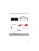
Front Panel Connector: JFP1/JFP2
The mainboard provides one front panel connector for electrical connection to
the front panel switches and LEDs. The JFP1 is compliant with Intel
®
Front Panel I/O
Connectivity Design Guide.
PIN SIGNAL DESCRIPTION
1 HD_LED_P Hard disk LED pull-up
2 FP PWR/SLP MSG LED pull-up
3 HD_LED_N Hard disk active LED
4 FP PWR/SLP MSG LED pull-up
5 RST_SW_N Reset Switch low reference pull-down to GND
6 PWR_SW_P Power Switch high reference pull-up
7 RST_SW_P Reset Switch high reference pull-up
8 PWR_SW_N Power Switch low reference pull-down to GND
9 RSVD_DNU Reserved. Do not use.
JFP1 Pin Definition
1
2
9
10
JFP1
HDD
LED
Reset
Switch
Power
LED
Power
Switch
7
8
Power
LED
Speaker
12
JFP2
PIN SIGNAL PIN SIGNAL
1 GND 2 SPK-
3 SLED 4 BUZ+
5 PLED 6 BUZ-
7 NC 8 SPK+
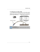
JFP2 Pin Definition
IrDA Infrared Module Header: JIR1 (Optional)
The connector allows you to connect to IrDA Infrared module. You must config-
ure the setting through the BIOS setup to use the IR function. JIR1 is compliant with
Intel
®
Front Panel I/O Connectivity Design Guide.
Pin Signal
1 IRRX
2 IRTX
3 GND
4 VCC5
5 NC
6 NC
Pin Definition
JIR1
1
2
5
6