Getting Started Chapter 1 Getting Started Thank you for choosing the K9A2 Platinum/ K9A2 Platinum V2 Series (MS-7376 v1.X) ATX mainboards. The K9A2 Platinum/ K9A2 Platinum V2 Series mainboards are based on AMD® 790FX & SB600 chipsets for optimal system efficiency. Designed to fit the advanced AM D ® Pheno m/Athlon/Se mpron proc es s ors in socket AM2+, the K9A2 Platinum/ K9A2 Platinum V2 Series deliver a high performance and professional desktop platform solution.
M S-7376 M ainboard Mainboard Specifications Processor Support - AMD® Phenom/Athlon/Sempron in the Socket AM2+ package. - Supports 4 pin CPU Fan Pin-Header with Fan Speed Control (For the latest information about CPU, please visit http://global.msi.com.tw/index.php?func=cpuform) Supported FSB - HyperTransport 3.0 supports speed up to 2600 MHz Chipset - North Bridge: AMD® 790FX chipset - South Bridge: AMD® SB600 chipset M emory Support - DDR2 1066/800/667/533 DRAM (240pin/ 1.
Getting Started RAID - SATA1~4 support RAID 0/ 1/ 0+1 mode - SATS5~6 & 2 eSATA ports support RAID0/ 1/ 0+1 mode (optional) Connectors Back panel - 1 PS/2 mouse port - 1 PS/2 keyboard port - 1 1394 port (optional) - 1 Optical SPDIF-out jack - 2 eSATA ports (optional) - 1 LAN jack - 4 USB 2.0 ports - 6 flexible audio jacks On-Board Pinheaders - 3 USB 2.
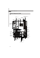
M S-7376 M ainboard Mainboard Layout CPUFAN1 Top : mouse Bottom: keyboar d 1394 Port (optional) Optical S/PDIF Out JPW1 ATX 1 USB ports Top: LAN Jack Bottom: USB ports PCI_EX1 PCI_EX2 IDE 1 DIMM4 DIMM3 SYSFAN4 DIMM2 AMD 790FX JPWR1 DIMM1 T: Line-In M : Line-Out B: Mic T:RS- Out M :CS-Out B:SS-Out SYSFAN1 Promise T3 PCI_EX3 SATA1 SATA2 SATA3 AMD SB600 PCI1 SATA2 LAN Chip PCI_EX4 SATA5 SATA6 Audio codec POWER PCI2 JCD1 VIA VT6308P (optional) PCI_EX5 JAUD1 JSLIC1 JFP1 BATT +
Getting Started CPUFAN1 Top : mouse Bottom: keyboar d 1394 Port (optional) Optical S/PDIF Out JPW1 ATX 1 USB por ts Top: LAN Jack Bottom: USB ports PCI_EX1 PCI_EX2 IDE 1 DIMM4 DIMM3 SYSFAN4 DIMM2 AMD 790FX JPWR1 DIMM1 T: Line-In M : Line-Out B: Mic T:RS-Out M :CS-Out B:SS-Out SYSFAN1 PCI_EX3 SATA1 SATA2 SATA3 AMD SB600 PCI1 SATA2 LAN Chip PCI_EX4 JFP2 Audio codec POWER PCI2 SYSFAN2 JCD1 VIA VT6308P (optional) PCI_EX5 JAUD1 JSLIC1 JFP1 BATT + RESET I/O Chip JBAT1 SPDOU
Hardware Setup Chapter 2 Hardware Setup This chapter provides you with the information about hardware setup procedures. While doing the installation, be careful in holding the components and follow the installation procedures. For some components, if you install in the wrong orientation, the components will not work properly. Use a grounded wrist strap before handling computer c om ponen ts . S tatic elec tric ity m ay damage the components.
M S-7376 M ainboard Quick Components Guide DDR2 DIMMs, p.2-6 JPWR1, p.2-8 JPW1, p.2-8 CPUFAN1, p.2-13 CPU, p.2-3 SYSFAN4, p.2-13 Back Panel I/O, p.2-9 ATX1, p.2-8 SYSFAN1, p.2-13 IDE1, p.2-11 JFP2, p.2-16 SATA1~6, p.2-12 PCI Slots, p.2-23 JCD1, p.2-13 JFP1, p.2-16 JTPM, p.2-14 SYSFAN2, p.2-13 JCOM1, p.2-16 PCI Express slots, p.2-20 FDD1, p.2-11 SPDOUT1, p.2-17 JSLIC1, p.2-15 JAUD1, p.2-14 JUSB1~3, p.2-15 SYSFAN3, p.2-13 POWER, p.2-19 J1394_1, p.2-17 2-2 JBAT1, p.2-18 RESET, p.
Hardware Setup CPU (Central Processing Unit) The mainboard supports AMD ® Phenom/Athlon/Sempron processors. The mainboard uses a CPU socket called Socket AM2+ for easy CPU installation. W hen you are installing the CPU, make sure the CPU has a heat sink and a cooling fan attached on the top to prevent overheating. If you do not have the heat sink and cooling fan, contact your dealer to purchase and install them before turning on the computer.
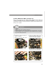
M S-7376 M ainboard CPU Installation Procedures for Socket AM2+ 1. Please turn off the power and unplug the power cord before installing the CPU. 2. Pull the lever s ideways away from the socket. Make sure to raise the lever up to a 90-degree angle. 3. Look for the gold arrow on the CPU. The gold arrow should point as shown in the picture. The CPU c an on l y f i t i n t h e c or r ec t orientation.Lower the CPU down onto the socket. 4.
Hardware Setup Installing AMD Socket AM2+ CPU Cooler Set W hen you are installing the CPU, make sure the CPU has a heat sink and a cooling fan attached on the top to prevent overheating. If you do not have the heat sink and cooling fan, contact your dealer to purchase and install them before turning on the computer. Important 1. Read the CPU status in BIOS (Chapter 3). 2. Mainboard photos shown in this section are for demonstration of the CPU/ cooler installation only.
M S-7376 M ainboard Memory These DIMM slots are used for installing memory modules. For more information on compatible components, please visit http://global.msi.com. tw/index.php?func=testreport DDR2 240-pin, 1.8V 56x2=112 pin 64x2=128 pin Dual-Channel Memory Population Rules In Dual-Channel mode, the memory modules can transmit and receive data with two data bus lines simultaneously. Enabling Dual-Channel mode can enhance the system performance.
Hardware Setup Installing Memory Modules 1. The memory module has only one notch on the center and will only fit in the right orientation. 2. Insert the memory module vertically into the DIMM slot. Then push it in until the golden finger on the memory module is deeply inserted in the DIMM slot. Important You can barely see the golden finger if the memory module is properly inserted in the DIMM slot. 3. The plastic clip at each side of the DIMM slot will automatically close.
M S-7376 M ainboard Power Supply ATX 24-Pin Power Connector: ATX1 This connector allows you to connect an ATX 24-pin power supply. To connect the ATX 24-pin power supply, make sure the plug of the power supply is inserted in the proper orientation and the pins are aligned. Then push down the power supply firmly into the connector. pin 13 You may use the 20-pin ATX power supply as you like.
Hardware Setup Back Panel LAN Mouse Line-In IEEE 1394 Port (optional) Keyboard RS-Out Line-Out CS-Out Optical eSATA Port S/PDIF-Out (optional) USB Port USB Port Mic SS-Out M ouse/Keyboard The standard PS/2® mouse/keyboard DIN connector is for a PS/2® mouse/keyboard. IEEE 1394 Port (optional) The 1394 port on the back panel provides connection to 1394 devices.
M S-7376 M ainboard Audio Ports These audio connectors are used for audio devices. You can differentiate the color of the audio jacks for different audio sound effects. Line-In (Blue) - Line In, is used for external CD player, tapeplayer or other audio devices. Line-Out (Green) - Line Out, is a connector for speakers or headphones. Mic (Pink) - Mic, is a connector for microphones. RS-Out (Black) - Rear-Surround Out in 4/ 5.1/ 7.1 channel mode. CS-Out (Orange) - Center/ Subwoofer Out in 5.1/ 7.
Hardware Setup Connectors Floppy Disk Drive Connector: FDD1 This connector supports 360KB, 720KB, 1.2MB, 1.44MB or 2.88MB floppy disk drive. FDD1 IDE Connector: IDE1 This connector supports IDE hard disk drives, optical disk drives and other IDE devices. IDE1 Important If you install two IDE devices on the same cable, you must configure the drives separately to master / slave mode by setting jumpers. Refer to IDE dev ic e’s doc umentation s upplied by the vendors for jumper s etting instructions.
M S-7376 M ainboard Serial ATA Connector: SATA1/ SATA2/ SATA3/ SATA4/ SATA5/ SATA6 (SATA5/ SATA6 are optinoal) This connector is a high-speed Serial ATA interface port. Each connector can connect to one Serial ATA device. SATA1/2/3/4 connectors are supported by SB600 SATA1 SATA2 SATA3 SATA4 SATA5 SATA6 SATA5/6 connectors are supported by Promise T3 (optional) Important Please do not fold the Serial ATA cable into 90-degree angle. Otherwise, data loss may occur during transmission.
Hardware Setup Fan Power Connectors: CPUFAN1, SYSFAN1~4 GND +12V SENSOR Control CPUFAN1 GND +12V NC SENSOR +1 2V GND SYSFAN1/2 SYSFAN4 GND +1 2V NC The fan power connectors support system cooling fan with +12V. W hen connecting the wire to the connectors, always note that the red wire is the positive and should be connected to the +12V; the black wire is Ground and should be connected to GND.
M S-7376 M ainboard Front Panel Audio Connector: JAUD1 This connector allows you to connect the front panel audio and is compliant with Intel® Front Panel I/O Connectivity Design Guide.
Hardware Setup Front USB Connector: JUSB1 / JUSB2 / JUSB3 This connector, compliant with Intel® I/O Connectivity Design Guide, is ideal for connecting high-speed USB interface peripherals such as USB HDD, digital cameras, M P3 players, printers, modems and the like.
M S-7376 M ainboard Front Panel Connectors: JFP1, JFP2 These connectors are for electrical connection to the front panel switches and LEDs. The JFP1 is compliant with Intel® Front Panel I/O Connectivity Design Guide.
Hardware Setup IEEE1394 Connector: J1394_1 (optional) This connector allows you to connect the IEEE1394 device via an optional IEEE1394 bracket.
M S-7376 M ainboard Jumper Clear CMOS Jumper: JBAT1 There is a CMOS RAM onboard that has a power supply from an external battery to keep the data of system configuration. W ith the CMOS RAM, the system can automatically boot OS every time it is turned on. If you want to clear the system configuration, set the jumper to clear data. 1 1 3 3 1 JBAT1 Keep Data Clear Data Important You can clear CMOS by shorting 2-3 pin while the system is off. Then return to 1-2 pin position.
Hardware Setup Button The motherboard provides the following buttons for you to set the computer’s function. This section will explain how to change your motherboard’s function through the use of button. Power Button: POWER This power button is used to turn-on or turn-off the system. Press the button to turnon or turn-off the system. POWER Reset Button: RESET This reset button is used to reset the system. Press the button to reset the system.
M S-7376 M ainboard Slots PCI (Peripheral Component Interconnect) Express Slot The PCI Express slot supports the PCI Express interface expansion card. The PCI Express 2.0x 16 supports up to 8.0 GB/s transfer rate. The PCI Express 2.0x 8 supports up to 4.0 GB/s transfer rate. ssThe PCI Express x1 supports up to 250 MB/s transfer rate. Mazarine PCI Express x16 Slots support up to PCI Express 2.
Hardware Setup ATi CrossFire (Multi-GPU) Technology ATi CrossFire (Multi-GPU) technology is an exciting new technology developed by ATI that allows the power of multiple Graphics. CrossFire requires a CrossFire Edition graphics card and a compatible standard Radeon (CrossFire Ready) graphics card from the same series.
M S-7376 M ainboard 3.W hen all of the hardware and software has been properly set up and installed, reboot the system. After entering the O.S., click the “Catalyst™ Control Center” icon on the desktop. There is a setting in the Catalyst™ Control Center that needs to be enabled for CrossFire™ to operate. The following aspect appears in Catalyst™ Control Center: Select the Advanced View f rom t h e view drop menu.
Hardware Setup PCI (Peripheral Component Interconnect) Slot The PCI slot supports LAN card, SCSI card, USB card, and other add-on cards that comply with PCI specifications. 32-bit PCI Slot PCI Interrupt Request Routing The IRQ, acronym of interrupt request line and pronounced I-R-Q, are hardware lines over which devices can send interrupt signals to the microprocessor.
BIOS Setup Chapter 3 BIOS Setup This chapter provides information on the BIOS Setup program and allows you to configure the system for optimum use. You may need to run the Setup program when: ² An error message appears on the screen during the system booting up, and requests you to run SETUP. ² You want to change the default settings for customized features.
M S-7376 M ainboard Entering Setup Power on the computer and the system will start POST (Power On Self Test) process. W hen the message below appears on the screen, press key to enter Setup. Press DEL to enter SETUP If the message disappears before you respond and you still wish to enter Setup, restart the system by turning it OFF and On or pressing the RESET button. You may also restart the system by simultaneously pressing , , and keys. Important 1.
BIOS Setup Control Keys < ↑> Move to the previous item < ↓> Move to the next item < ←> Move to the item in the left hand < →> Move to the item in the right hand Select the item Jumps to the Exit menu or returns to the main menu from a submenu <+/PU> Increase the numeric value or make changes <-/PD> Decrease the numeric value or make changes Load Optimized Defaults Save configuration changes and exit setup Getting Help After entering the Setup menu, the first men
M S-7376 M ainboard The Main Menu Standard CM OS Features Use this menu for basic system configurations, such as time, date etc. Advanced BIOS Features Use this menu to setup the items of AMI® special enhanced features. Integrated Peripherals Use this menu to specify your settings for integrated peripherals. Power M anagement Setup Use this menu to specify your settings for power management. PNP/PCI Configurations This entry appears if your system supports PnP/PCI.
BIOS Setup Load Fail-Safe Defaults Use this menu to load the default values set by the BIOS vendor for stable system performance. Load Optimized Defaults Use this menu to load the default values set by the mainboard manufacturer specifically for optimal performance of the mainboard. BIOS Setting Password Use this menu to set the password for BIOS. Save & Exit Setup Save changes to CMOS and exit setup. Exit Without Saving Abandon all changes and exit setup.
M S-7376 M ainboard Standard CMOS Features The items in Standard CMOS Features Menu includes some basic setup items. Use the arrow keys to highlight the item and then use the or keys to select the value you want in each item. Date (MM:DD:YY) This allows you to set the system to the date that you want (usually the current date). The format is . day Day of the week, from Sun to Sat, determined by BIOS. Read-only. mon th The month from Jan. through Dec.
BIOS Setup Device/ Vender/ Size It will showing the device information that you connected to the IDE/SATA connector. LBA/Large M ode This allows you to enable or disable the LBA Mode. Setting to Auto enables LBA mode if the device supports it and the devices is not already formatted with LBA mode disabled. DM A M ode Select DMA Mode. Hard Disk S.M.A.R.T. This allows you to activate the S.M.A.R.T. (Self-Monitoring Analysis & Reporting Technology) capability for the hard disks. S.M.A.R.
M S-7376 M ainboard Advanced BIOS Features Boot Sector Protection W hen you enable this item and someone attempt to write data into this area, BIOS will show a warning message on screen and it will alarm beep. Full Screen LOGO Display This item enables you to show the company logo on the bootup screen. Settings are: [Enabled] Shows a still image (logo) on the full screen at boot. [Disabled] Shows the POST messages at boot.
BIOS Setup MPS Table Version This field allows you to select which MPS (Multi-Processor Specification) version to be used for the operating system. You need to select the MPS version supported by your operating system. To find out which version to use, consult the vendor of your operating system. Chipset Feature Press to enter the sub-menu and the following screen appears: HPET The HPET (High Precision Event Timers) is a component that is part of the chipset.
M S-7376 M ainboard Integrated Peripherals USB Controller This setting allows you to enable/disable the onboard USB 1.1/ 2.0 controller. USB Device Legacy Support Select [Enabled] if you need to use a USB-interfaced device in the operating system. Onboard LAN Controller This setting allows you to enable/disable the onboard LAN controller. LAN Option ROM This item is used to decide whether to invoke the Boot ROM of the onboard LAN.
BIOS Setup Extra RAID Controller (for Promise RAID, optional) This item allows you to enable/disable the onboard extra RAID controller. Important If you intend to use a extra RAID function card, you have to disable the “Extra RAID Controller” item. HW HD Audio Controller This setting is used to enable/disable the HD audio controller.
M S-7376 M ainboard Power Management Setup Important S3-related functions described in this section are available only when your BIOS supports S3 sleep mode. ACPI Function This item is to activate the ACPI (Advanced Configuration and Power Management Interface) Function. If your operating system is ACPI-aware, such as Windows 98SE/ 2000/ME/ XP, select [Enabled]. ACPI Standby State This item specifies the power saving modes for ACPI function.
BIOS Setup Suspend Time Out (M inute) If system activity is not detected for the length of time specified in this field, all devices except CPU will be shut off. Power Button Function This feature sets the function of the power button. Settings are: [Power On/ Off] The power button functions as normal power on/ off button. [Suspend] W hen you press the power button, the computer enters the suspend/sleep mode, but if the button is pressed for more than four seconds, the computer is turned off.
M S-7376 M ainboard Resume by PCIE Device W hen set to [Enabled], the feature allows your system to be awakened from the power saving modes through any event on PCIE device. Resume by RTC Alarm The field is used to enable or disable the feature of booting up the system on a scheduled time/date.
BIOS Setup PNP/PCI Configurations This section describes configuring the PCI bus system and PnP (Plug & Play) feature. PCI, or Peripheral Component Interconnect, is a system which allows I/O devices to operate at speeds nearing the speed the CPU itself uses when communicating with its special components. This section covers some very technical items and it is strongly recommended that only experienced users should make any changes to the default settings.
M S-7376 M ainboard IRQ Resource Setup Press to enter the sub-menu and the following screen appears. IRQ 3/4/5/7/9/10/11/14/15 These items specify the bus where the specified IRQ line is used. The settings determine if AMIBIOS should remove an IRQ from the pool of available IRQs passed to devices that are configurable by the system BIOS. The available IRQ pool is determined by reading the ESCD NVRAM.
BIOS Setup H/W Monitor Chassis Intrusion The field enables or disables the feature of recording the chassis intrusion status and issuing a warning message if the chassis is once opened. To clear the warning message, set the field to [Reset]. The setting of the field will automatically return to [Enabled] later. CPU Smart FAN Target The mainboard provides the Smart Fan function which can control the CPU fan speed automatically depending on the current temperature to keep it with in a specific range.
M S-7376 M ainboard Cell Menu Important Change these settings only if you are familiar with the chipset. Current CPU Clock/ DRAM Frequency These items show the current clocks of CPU and Memory frequency. Read-only. D.O.T.3 Step 3/ 1/ 2 setting The D.O.T.3 has 3 steps to overclock the CPU/ PCIE, you can set the overclocking percentage for each step. W hen the CPU loading reaches to 20%, the CPU/ PCIE frequencies will overclock according the setting of step1.
BIOS Setup AMD Cool’n’Quiet The Cool’n’ Quiet technology can effectively and dynamically lower CPU speed and power consumption. Important To ensure that Cool’n’Quiet function is activated and will be working properly, it is required to double confirm that: 1. Run BIOS Setup, and select Cell Menu. Under Cell M enu, find AM D Cool’n’Q uiet, and s et this item to “Enable.” 2. Enter Windows , and select [Start]-> [Settings]->[Control Pannel]->[Power Options].
M S-7376 M ainboard DRAM Timing Mode Setting to [Auto] enables DRAM CAS# Latency automatically to be determined by BIOS based on the configurations on the SPD (Serial Presence Detect) EEPROM on the DRAM module. Bank Interleaving This field selects 2-bank or 4-bank interleave for the installed SDRAM. Disable the function if 16MB SDRAM is installed. 1T/2T M emory Timing This field controls the SDRAM command rate. Selecting [1T] makes SDRAM signal controller to run at 1T (T=clock cycles) rate.
BIOS Setup Important 1. If you do not have any EMI problem, leave the setting at [Disabled] for optimal system stability and performance. But if you are plagued by EMI, select the value of Spread Spectrum for EMI reduction. 2. The greater the Spread Spectrum value is, the greater the EMI is reduced, and the system will become less stable. For the most suitable Spread Spectrum value, please consult your local EMI regulation. 3.
M S-7376 M ainboard USER SETTINGS Save Settings 1/ 2 These items are used to save the settings set by yourself to CMOS. Load Settings 1/ 2 These items are available after you save your settings in Save Settings 1/ 2 items , and are used to load the settings from CMOS.
BIOS Setup Load Fail-Safe/ Optimized Defaults The two options on the main menu allow users to restore all of the BIOS settings to the default Fail-Safe or Optimized values. The Optimized Defaults are the default values set by the mainboard manufacturer specifically for optimal performance of the mainboard. The Fail-Safe Defaults are the default values set by the BIOS vendor for stable system performance.
M S-7376 M ainboard BIOS Setting Password W hen you select this function, a message as below will appear on the screen: Type the password, up to six characters in length, and press . The password typed now will replace any previously set password from CMOS memory. You will be prompted to confirm the password. Retype the password and press . You may also press to abort the selection and not enter a password.
SATA RAID Appendix C SATA RAID The SB600 and T3 (optional) integrate one SATA host controller separately, and support RAID function for performance and reliability. SATA RAID provides support for RAID 0 (Striping), RAID 1 (Mirroring), RAID 0+1 (Striping & Mirroring). RAID 0 greatly improves h ard d is k I/O p erf or manc e by concurrently striping data across multiple drives. RAID 1 makes sure data is not lost if a drive fails as data is simultaneously written to two drives.
M S-7376 M ainboard RAID Configuration Creating and deleting RAID set and performing other RAID setting up operations are done in the RAID BIOS. During bootup, a screen similar to the one below will appear for about few seconds. Press to enter FastBuild utility. Important Be sure to enable the RAID function for SATA device in BIOS (please refer the Intergrated Peripherals s ec tion in BIOS) before configuting the Fastbuild Utility. The FastBuild menu screen will appear.
SATA RAID View Drives Assignments This window displays the model number, capacities and assignment of the drives physically attached to the SATA host adapter. Important Please visit the MSI websit (http://www.msi.com.tw/ ) to get the Promise T3 RAID application program for more Promise RAID applications.
M S-7376 M ainboard Define LD (Creating RAID) The selection of the RAID configuration should be based upon factors including performance, data security, and the number of drives available. It is best to carefully consider the long-term role of the system and plan the data storage strategy. RAID sets can be created either automatically, or to allow the greatest flexibility, manually. 1. Press 2 on the Main Menu screen to enter the Define LD Menu. 2.
SATA RAID • Stripe Block Size, the default 64KB is best for most applications. RAID 0 or 10 only. • Gigabyte Boundary, allows use of slightly smaller replacement drives. • Cache Mode, W riteThru or W riteBack. 4. On the Drives Assignments window, use the arrow key to choose the hard drives which you want to make part of the LD, use the space key to change the assignment to “Y”. Then press [Ctrl+Y] to save the configuration. 5.
M S-7376 M ainboard 6. The LD creation is done, the screen shows the LD information as below. Press ESC key to the main screen. 7. Press ESC key to exit the utility, a message “System is going to REBOOT! Are You Sure?” will display, answer “Y” to exit it and the system will reboot.
SATA RAID Delete LD (Deleting RAID) 1. Select “Delete LD” on the main screen. 2. Choose a LD No you want to delete and press “Del” or “Alt+D” delete the RAID set. 3. On the next screen, a message will display to inform you, press “Ctrl+Y” to delete the RAID set or other key to abort it. Press “Ctrl+Y” to complete the deletion.
M S-7376 M ainboard Installing the RAID Driver (for bootable RAID Array) For W indows XP: 1. After you complete the RAID BIOS setup, boot from the W indows CD, and the W indows XP Setup program starts. 2. Press F6 and wait for the W indows Setup screen to appear. 3. Insert the floppy that contains the RAID driver,Press the “S” key to select “Specify Additional Device”. Important Please follow the instruction below to make a SATA RAID driver for yourself. 1. Insert the MSI CD into the CD-ROM drive. 2.
SATA RAID Installing the RAID Driver Under Windows (for Non-bootable RAID Array) 1. Insert the MSI CD into the CD-ROM drive. 2. The CD will auto-run and the setup screen will appear. 3. Under the Driver tab, click on ATI System Driver or Promise PDC42819 Driver by your need. The ATI System Driver includes RAID Driver. 4. The driver will be automatically installed. Important You must install the RAID driver to enable RAID.