KT6 Delta MS-6590 (v2.X) ATX Mainboard Version 2.
Manual Rev: 2.0 Release Date: July 2003 FCC-B Radio Frequency Interference Statement This equipment has been tested and found to comply with the limits for a class B digital device, pursuant to part 15 of the FCC rules. These limits are designed to provide reasonable protection against harmful interference when the equipment is operated in a commercial environment.
Copyright Notice The material in this document is the intellectual property of MICRO-STAR INTERNATIONAL. We take every care in the preparation of this document, but no guarantee is given as to the correctness of its contents. Our products are under continual improvement and we reserve the right to make changes without notice. Trademarks All trademarks are the properties of their respective owners. AMD, Athlon™, Athlon™ XP, Thoroughbred™, and Duron™ are registered trademarks of AMD Corporation.
Safety Instructions 1. 2. 3. 4. 5. 6. 7. 8. 9. 10. 11. 12. Always read the safety instructions carefully. Keep this User’s Manual for future reference. Keep this equipment away from humidity. Lay this equipment on a reliable flat surface before setting it up. The openings on the enclosure are for air convection hence protects the equipment from overheating. Do not cover the openings. Make sure the voltage of the power source and adjust properly 110/220V before connecting the equipment to the power inlet.
CONTENTS FCC-B Radio Frequency Interference Statement ........................................... ii Copyright Notice .......................................................................................... iii Revision History ........................................................................................... iii Technical Support ......................................................................................... iii Safety Instructions ......................................................
Back Panel ............................................................................................ 2-9 Mouse Connector ......................................................................... 2-9 Keyboard Connector ................................................................... 2-10 USB 2.0 Connectors .................................................................... 2-10 Serial Port Connectors: COM A & COM B .................................. 2-11 RJ-45 LAN Jack (Optional) .....................
PCI Interrupt Request Routing .................................................... 2-32 Chapter 3. BIOS Setup .............................................................................. 3-1 Entering Setup ...................................................................................... 3-2 Selecting the First Boot Device ..................................................... 3-2 Control Keys ................................................................................. 3-3 Getting Help ...........
Getting Started Chapter 1. Getting Started Getting Started Thank you for purchasing KT6 Delta (MS-6590 v2.X) ATX mainboard. The KT6 Delta is based on VIA® Apollo KT600 & VT8237 chipsets and provides eight USB 2.0 ports for highspeed data transmission, C-Media 9739A chip for 6-channel audio output and one SPDIF pinheader for digital audio transmission.
MS-6590 ATX Mainboard Mainboard Specifications CPU h Supports Socket A (Socket-462) for AMD® Athlon™/Athlon™ XP /Duron™ processors. h Supports up to 3200+. Chipset h VIA® Apollo KT600 chipset - FSB @200/266/333/400 MHz. - Supports DDR200/266/333/400 DDR SDRAM. -AGP 8X and PCI advanced high performance memory controller. h VIA® VT8237 chipset - Ultra DMA 66/100/133 master mode EIDE controller.
Getting Started Promise 20378 On-Board (Optional) h Supports Ultra ATA, Serial ATA, Ultra ATA RAID 0 or 1 , Serial ATA RAID 0 or 1, Ultra/Serial ATA RAID 0+1 supported. h Connect up to 2 Serial ATA devices and 2 Ultra ATA 133 devices. On-Board Peripherals h On-Board Peripherals include: - 1 floppy port supports 2 FDDs with 360K, 720K, 1.2M, 1.44M and 2.88Mbytes - 2 serial ports (COM A + COM B) - 1 parallel port supports SPP/EPP/ECP mode - 1 IrDA connector for SIR/ASKIR/HPSIR - 1 audio port - 8 USB 2.
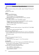
MS-6590 ATX Mainboard Mainboard Layout Top : mouse Bottom : keyboard CFAN1 FDD 1 Bottom : COM A COM B US B ports VIA KT600 IDE 1 Top : Parallel Port IDE 2 ATX Power Supply SOCKET 462 Top: LAN jack (Optional) Bottom : US B ports Line-Out Line-In Mic J6 DDR 1 AGP Slot DDR 2 JIR1 DDR 3 NBFAN1 JPW1 Winbond W83697HF BIOS PCI Slot 1 PCI Slot 2 BATT + VT8237 PCI Slot 3 JBAT1 SFAN1 J3 IDE 3 (Optional) PCI Slot 4 JS1 PCI Slot 5 VIA VT6306 (Optional) PROMISE PDC20378 (Optional) SER1
Getting Started MSI Special Features Super Pack (Optional) MSI provides a useful CD which includes 6 powerful and popular utilities for your office professional working and for your home leisure entertainments. 1. 2. 3. 4. 5. 6. 1 4 2 5 3 6 Adobe Photoshop Album: The fast and easy way to organize and share your lifetime of photos. Media Ring: A high quality voice service for PC users to make international calls without the elevated cost of traditional IDD providers.
MS-6590 ATX Mainboard Core Center The Core Center is a new utility you can find in the CD-ROM disk. The utility is just like your PC doctor that can detect, view and adjust the PC hardware and system status during real time operation. In the left side it shows the current system status including the Vcore, 3.3V, +5V and 12V. In the right side it shows the current PC hardware status such as the CPU & system temperatures and all fans speeds.
Getting Started Left-side: Current system status In the left sub-menu, you can configure the settings of FSB, Vcore, Memory Voltage and AGP Voltage by clicking the radio button in front of each item and make it available (the radio button will be lit as yellow when selected), use the “+” and “-” buttons to adjust, then click “OK” to apply the changes. Then you can click Save to save the desired FSB you just configured.
MS-6590 ATX Mainboard Core CellTM Chip By diagnosing the current system utilization, the CoreCell™ Chip automatically tunes your motherboard to the optimal state, leading to less noise, longer duration, more powersaving and higher performance. Features of CoreCell™ Speedster -- Advanced O.C. design. -- Superior O.C. capability. -- Greater O.C. method. BuzzFree -- Diagnoses current system utilization & temperature. -- Controls both CPU and NorthBridge fans. -- Cuts up to 50% of system noise.
Getting Started Live BIOS™/Live Driver™ The Live BIOS™/Live Driver™ is a tool used to detect and update your BIOS/drivers online so that you don’t need to search for the correct BIOS/driver version throughout the Web site. To use the function, you need to install the “MSI Live Update 2” application. After installation, the “MSI Live Update 2” icon (as shown on the right) will appear on the screen.
MS-6590 ATX Mainboard D-Bracket™ 2 (Optional) D-Bracket™ 2 is an external USB bracket integrating four Diagnostic LEDs, which use graphic signal display to help users understand their system. The LEDs provide up to 16 combinations of signals to debug the system. The 4 LEDs can debug all problems that fail the system, such as VGA, RAM or other failures. This special feature is very useful for the overclocking users. These users can use the feature to detect if there are any problems or failures.
Getting Started TM D-Bracket 2 Description Processor Initialization 1 3 2 4 - This will show information regarding the processor (like brand name, system bus, etc…) Testing RTC (Real Time Clock) Initializing Video Interface - This will start detecting CPU clock, checking type of video onboard. Then, detect and initialize the video adapter. BIOS Sign On - This will start showing information about logo, processor brand name, etc….
MS-6590 ATX Mainboard Color Management MSI has an unified color management rule for some connectors on the mainboards, which helps you to install the memory modules, expansion cards and other peripherals devices more easily and conveniently. h Single DDR DIMMs: Light green h Intel spec IDE ATA66/100 connector: 1st IDE in blue, 2nd IDE in white h IDE ATA133 connector: yellow h Serial ATA150 connector: orange h AGP 8X slot: red h 1394 connector: dark green h USB 2.
Getting Started Round Cable (Optional) Round cable is an enhanced cable for PCI IDE and Ultra DMA controller. It has the following benefits: h Data transfer rate started by 133MB/s h Backward compatibility (ATA33/66/100/133) h Higher performance than traditional Flat cable (data rate) h Improved data robustness h Better airflow due to thinner ATA/133 cable Connect to the slave drives. Connect to the master hard disk drives. Connect to the system connectors on the mainboard.
MS-6590 ATX Mainboard S-Bracket (Optional) S-Bracket is a bracket which provides 2 SPDIF jacks for digital audio transmission and 2 analog Line-Out connectors for additional 4-channel analog audio output. With the S-Bracket, your system will be able to perform 6channel audio operation for wonderful surround sound effect, or connect to Sony & Philips Digital Interface (SPDIF) speakers for audio transmission with better quality.
Hardware Setup Chapter 2. Hardware Setup Hardware Setup This chapter tells you how to install the CPU, memory modules, and expansion cards, as well as how to setup the jumpers on the mainboard. Also, it provides the instructions on connecting the peripheral devices, such as the mouse, keyboard, etc. While doing the installation, be careful in holding the components and follow the installation procedures.
MS-6590 ATX Mainboard Quick Components Guide CPU, p.2-3 CFAN1, p.2-15 DDR DIMMs, p.2-6 JWR1, p.2-8 Back Panel I/O, p.2-9 FDD1, p.2-14 IDE1 & IDE2, p.2-16 J6, p.2-28 NBFAN1, p.2-15 JPW1, p.2-8 JIR1, p.2-25 AGP Slot, p.2-31 SATA2, p.2-17 SATA1, p.2-17 SFAN1, p.2-15 PCI Slots, p.2-31 JBAT1, p.2-29 J3, p.2-20 IDE3, p.2-18 SER2, p.2-18 SER1, p.2-18 JS1, p.2-30 JLED1, p.2-27 JAUD1, p.2-25 JFP2, p.2-24 JSP3, p.2-20 JFP1, p.2-24 J1394_0, J1394_1, J1394_2 , p.2-22 2-2 JUSB1, p.
Hardware Setup Central Processing Unit: CPU The mainboard supports AMD® Athlon™, Athlon™ XP and Duron™ processors in the 462 pin package. The mainboard uses a CPU socket called Socket-462 for easy CPU installation. When you are installing the CPU, make sure the CPU has a heat sink and a cooling fan attached on the top to prevent overheating. If you do not find the heat sink and cooling fan, contact your dealer to purchase and install them before turning on the computer.
MS-6590 ATX Mainboard CPU Installation Procedures for Socket 462 1. Please turn off the power and unplug the power cord before installing the CPU. 2. Pull the lever sideways away from the socket. Make sure to raise the lever up to a 90degree angle. 3. Look for the gold arrow. The gold arrow should point towards the lever pivot. The CPU can only fit in the correct orientation. 4. If the CPU is correctly installed, the pins should be completely embedded into the socket and can not be seen.
Hardware Setup Installing AMD Athlon CPU (Socket 462) Cooler Set The following instructions will guide you through the heat sink installation procedures. Please consult your agent for the proper CPU cooler set. 1. Position your CPU cooler set onto the CPU. Apply some heat sink paste 2. Use one end of the clip to hook the latch of the CPU sliding plate. 3. Hook the other latch to fix the cooling fan set. You may need a screw drive to press down the other side of the clip. 4.
MS-6590 ATX Mainboard Memory The mainboard provides 3 slots for 184-pin DDR SDRAM DIMM (Double In-Line Memory Module) modules and supports the memory size up to 3GB. You can install PC3200/DDR400, PC2700/DDR333, PC2100/ DDR266 or PC1600/DDR200 modules on the DDR DIMM slots (DDR 1~3). DDR DIMM Slots (DDR 1~3) Introduction to DDR SDRAM DDR (Double Data Rate) SDRAM is similar to conventional SDRAM, but doubles the rate by transferring data twice per cycle. It uses 2.5 volts as opposed to 3.
Hardware Setup DDR DIMM Module Combination Install at least one DIMM module on the slots. Memory modules can be installed on the slots in any order. You can install either single- or doublesided modules to meet your own needs.
MS-6590 ATX Mainboard Power Supply The mainboard supports ATX power supply for the power system. Before inserting the power supply connector, always make sure that all components are installed properly to ensure that no damage will be caused. ATX 20-Pin Power Connector: JWR1 This connector allows you to connect to an ATX power supply. To connect to the ATX power supply, make sure the plug of the power supply is inserted in the proper orientation and the pins are aligned.
Hardware Setup Back Panel The back panel provides the following connectors: LAN (Optional) Parallel Mouse Keyboard COM A COM B USB Ports USB Ports L-in L-out MIC Mouse Connector The mainboard provides a standard PS/2® mouse mini DIN connector for attaching a PS/2® mouse. You can plug a PS/2® mouse directly into this connector.
MS-6590 ATX Mainboard Keyboard Connector The mainboard provides a standard PS/2® keyboard mini DIN connector for attaching a PS/2® keyboard. You can plug a PS/2® keyboard directly into this connector. Pin Definition 6 5 3 4 1 2 PS/2 Keyboard (6-pin Female) PIN SIGNAL DESCRIPTION 1 2 3 4 5 6 Keyboard DATA NC GND VCC Keyboard Clock NC Keyboard DATA No connection Ground +5V Keyboard clock No connection USB 2.
Hardware Setup Serial Port Connectors: COM A & COM B The mainboard offers two 9-pin male DIN connectors as serial port COM A & COM B. The ports are 16550A high speed communication ports that send/receive 16 bytes FIFOs. You can attach a serial mouse or other serial devices directly to the connectors.
MS-6590 ATX Mainboard Parallel Port Connector: LPT1 The mainboard provides a 25-pin female centronic connector as LPT. A parallel port is a standard printer port that supports Enhanced Parallel Port (EPP) and Extended Capabilities Parallel Port (ECP) mode.
Hardware Setup Audio Port Connectors Line Out is a connector for Speakers or Headphones. Line In is used for external CD player, Tape player, or other audio devices. Mic is a connector for microphones. Line In 1/8” Stereo Audio Connectors Line Out MIC MSI Reminds You... For advanced audio application, CMedia 9739A is provided to offer support for 6-channel audio operation and can turn rear audio connectors from 2-channel to 4-/6-channel audio.
MS-6590 ATX Mainboard Connectors The mainboard provides connectors to connect to FDD, IDE HDD, case, LAN, USB Ports, IR module and CPU/System/Power Supply FAN. Floppy Disk Drive Connector: FDD1 The mainboard provides a standard floppy disk drive connector that supports 360K, 720K, 1.2M, 1.44M and 2.88M floppy disk types.
Hardware Setup Fan Power Connectors: CFAN1/SFAN1/NBFAN1 The CFAN1 (processor fan), SFAN1 (system fan) and NBFAN1 (NorthBridge fan) support system cooling fan with +12V. It supports threepin head connector. When connecting the wire to the connectors, always take note that the red wire is the positive and should be connected to the +12V, the black wire is Ground and should be connected to GND.
MS-6590 ATX Mainboard Hard Disk Connectors: IDE1 & IDE2 The mainboard has a 32-bit Enhanced PCI IDE and Ultra DMA 66/100/ 133 controller that provides PIO mode 0~4, Bus Master, and Ultra DMA 66/ 100/133 function. You can connect up to four hard disk drives, CD-ROM, 120MB Floppy and other devices. IDE1 IDE2 IDE1 (Primary IDE Connector) The first hard drive should always be connected to IDE1. IDE1 can connect a Master and a Slave drive.
Hardware Setup Serial ATA/Serial ATA RAID Connectors controlled by VT8237: SATA1 & SATA2 The Southbridge of this mainboard is VIA VT8237 which supports two serial connectors SATA1& SATA2. SATA1 & SATA2 are dual high-speed Serial ATA interface ports. Each supports 1st generation serial ATA data rates of 150 MB/s. Both connectors are fully compliant with Serial ATA 1.0 specifications. Each Serial ATA connector can connect to 1 hard disk device.
MS-6590 ATX Mainboard Hard Disk RAID Connectors controlled by Promise20378: IDE3, SER1 & SER2 (Optional) The brand new Promise 20378 chipset supports one IDE connector IDE3 and two serial connectors SER1& SER2. IDE3 is a 32-bit Enhanced PCI IDE and Ultra DMA 66/100/133 controller that provides PIO mode 0~6, Bus Master, and Ultra DMA 66/100/133 function. You can connect up to 2 hard disk drives---one IDE master and one IDE slave. And SER1 & SER2 are dual high-speed Serial ATA interface ports.
Hardware Setup SER1 & SER2 Pin Definition Pin Signal 1 3 5 7 GND TXN RXN GND Optional Serial ATA cable Pin Signal 2 4 6 TXP GND RXP Take out the dust cover and connect to the hard disk devices Connect to SER1 or SER2 MSI Reminds You... Please do not fold the serial ATA cable in a 90-degree angle, which will cause the loss of data during the transmission.
MS-6590 ATX Mainboard CD-In Connector: J3 The connector is for CD-ROM audio connector. S-Bracket (SPDIF) Connector: JSP3 (Optional) The connector allows you to connect a S-Bracket for Sony & Philips Digital Interface (SPDIF). The S-Bracket offers 2 SPDIF jacks for digital audio transmission (one for optical fiber connection and the other for coaxial), and 2 analog Line-Out jacks for 4-channel audio output.
Hardware Setup JSP3 Pin Definition PIN SIGNAL DESCRIPTION PIN SIGNAL 1 VCC5 VCC 5V 2 VDD3 VDD 3.
MS-6590 ATX Mainboard IEEE 1394 Connectors: J1394_0, J1394_1, J1394_2 (Optional) The mainboard provides three 1394 pin headers that allow you to connect optional IEEE 1394 ports.
Hardware Setup How to attach the IEEE 1394 Port: 1394 Port Connected separately to J1394_1, J1394_2 and J1394_3.
MS-6590 ATX Mainboard Front Panel Connectors: JFP1 & JFP2 The mainboard provides two front panel connectors for electrical connection to the front panel switches and LEDs. JFP1 is compliant with Intel® Front Panel I/O Connectivity Design Guide.
Hardware Setup Front Panel Audio Connector: JAUD1 The JAUD1 front panel audio connector allows you to connect to the front panel audio and is compliant with Intel® Front Panel I/O Connectivity Design Guide.
MS-6590 ATX Mainboard Front USB Connectors: JUSB1 The mainboard provides one USB 2.0 pin headers JUSB1 that is compliant with Intel® I/O Connectivity Design Guide. USB 2.0 technology increases data transfer rate up to a maximum throughput of 480Mbps, which is 40 times faster than USB 1.1, and is ideal for connecting high-speed USB interface peripherals such as USB HDD, digital cameras, MP3 players, printers, modems and the like.
Hardware Setup D-Bracket™ 2 Connector: JLED1 (Optional) The mainboard comes with a JLED1 connector for you to connect to DBracket™ 2. D-Bracket™ 2 is a USB Bracket that supports both USB1.1 & 2. 0 spec. It integrates four LEDs and allows users to identify system problem through 16 various combinations of LED signals. For definitions of 16 signal combinations, please refer to D-Bracket™ 2 in Chapter 1.
MS-6590 ATX Mainboard Chassis Intrusion Switch Connector: J6 This connector is connected to a 2-pin chassis switch. If the chassis is opened, the switch will be short. The system will record this status and show a warning message on the screen. To clear the warning, you must enter the BIOS utility and clear the record. 2 1 GND CINTRU J6 IrDA Infrared Module Header: JIR1 The connector allows you to connect to IrDA Infrared module.
Hardware Setup Jumpers The motherboard provides the following jumpers for you to set the computer’s function. This section will explain how to change your motherboard’s function through the use of jumpers. Clear CMOS Jumper: JBAT1 There is a CMOS RAM on board that has a power supply from external battery to keep the data of system configuration. With the CMOS RAM, the system can automatically boot OS every time it is turned on.
MS-6590 ATX Mainboard Center/Subwoofer Speaker Setting Jumper: JS1 This jumper helps to configure the center and subwoofer audio signals. If you have the optional S-Bracket with your mainboard, be sure to remove the jumper, otherwise the 6-channel audio will not work probably. If you do not have S-Bracket, keep the jumper on to use the 6-channel audio. For more information on the S-Bracket, please refer p.
Hardware Setup Slots The motherboard provides one AGP slot and five 32-bit PCI bus slots. AGP Slot PCI Slots AGP (Accelerated Graphics Port) Slot The AGP slot allows you to insert the AGP graphics card. AGP is an interface specification designed for the throughput demands of 3D graphics. It introduces a 66MHz, 32-bit channel for the graphics controller to directly access main memory. The slot supports 4x (1.07Gbps) and 8x (2.1Gbps) AGP cards.
MS-6590 ATX Mainboard PCI Interrupt Request Routing The IRQ, acronym of interrupt request line and pronounced I-R-Q, are hardware lines over which devices can send interrupt signals to the microprocessor.
BIOS Setup Chapter 3. BIOS Setup BIOS Setup This chapter provides information on the BIOS Setup program and allows you to configure the system for optimum use. You may need to run the Setup program when: An error message appears on the screen during the system booting up, and requests you to run SETUP. You want to change the default settings for customized features.
MS-6590 ATX Mainboard Entering Setup Power on the computer and the system will start POST (Power On Self Test) process. When the message below appears on the screen, press key to enter Setup. DEL:Setup F11:Boot Menu F12:Network boot TAB:Logo If the message disappears before you respond and you still wish to enter Setup, restart the system by turning it OFF and On or pressing the RESET button. You may also restart the system by simultaneously pressing , , and keys.
BIOS Setup Control Keys <↑> <↓> <←> <→> <+/PU> <-/PD> Move to the previous item Move to the next item Move to the item in the left hand Move to the item in the right hand Select the item Jumps to the Exit menu or returns to the main menu from a submenu Increase the numeric value or make changes Decrease the numeric value or make changes Load High Performance Defaults Load Optimal Defaults BIOS Languages switch Save all the CMOS changes and exit Getting Help After enteri
MS-6590 ATX Mainboard The Main Menu Once you enter AMIBIOS NEW SETUP UTILITY, the Main Menu will appear on the screen. The Main Menu displays twelve configurable functions and two exit choices. Use arrow keys to move among the items and press to enter the sub-menu. Standard CMOS Features Use this menu for basic system configurations, such as time, date etc. Advanced BIOS Features Use this menu to setup the items of AMI® special enhanced features.
BIOS Setup Frequency/Voltage Control Use this menu to specify your settings for frequency/voltage control. Set Supervisor Password Use this menu to set Supervisor Password. Set User Password Use this menu to set User Password. Load High Performance Defaults Use this menu to load the BIOS values for the best system performance, but the system stability may be affected. Load BIOS Setup Defaults Use this menu to load factory default settings into the BIOS for stable system performance operations.
MS-6590 ATX Mainboard Standard CMOS Features The items inside STANDARD CMOS SETUP menu are divided into 9 categories. Each category includes none, one or more setup items. Use the arrow keys to highlight the item you want to modify and use the or keys to switch to the value you prefer. System Time This allows you to set the system time that you want (usually the current time). The time format is .
BIOS Setup Type Cylinders Heads Write Precompensation Sectors Maximum Capacity LBA Mode Block Mode Fast Programmed I/O Modes 32 Bit Transfer Mode Select how to define the HDD parameters Enter cylinder number Enter head number Enter write precomp cylinder Enter sector number Read the maximal HDD capacity Select Auto for a hard disk > 512 MB under Windows and DOS, or Disabled under Netware and UNIX Select Auto to enhance the hard disk performance Select Auto to enhance hard disk performance by optimizing t
MS-6590 ATX Mainboard Advanced BIOS Features Quick Boot Setting the item to Enabled allows the system to boot within 5 seconds since it will skip some check items. Available options: Enabled, Disabled. Full Screen Logo Show This item enables you to show the company logo on the bootup screen. Settings are: Enabled Shows a still image (logo) on the full screen at boot. Disabled Shows the POST messages at boot. Boot Sequence Press to enter the sub-menu screen.
BIOS Setup 1st/2nd/3rd Boot Device The items allow you to set the sequence of boot devices where AMIBIOS attempts to load the operating system. The settings are: IDE-0 The system will boot from the first HDD. IDE-1 The system will boot from the second HDD. IDE-2 The system will boot from the third HDD. IDE-3 The system will boot from the fourth HDD. Floppy The system will boot from floppy drive.
MS-6590 ATX Mainboard USB RMD-FDD The system will boot from any USB-interface ARMD device, such as LS-120 or ZIP drive, that functions as a floppy drive. USB RMD-HDD The system will boot from USB-interface ARMD device, such as MO or ZIP drive, that functions as hard disk drive. Disabled Disable this sequence. MSI Reminds You... Available settings for “1st/2nd/3rd Boot Device” vary depending on the bootable devices you have installed.
BIOS Setup Primary Display This configures the primary subsystem in the computer. Available options: Mono (monochrome), CGA40x25, CGA80x25, VGA/EGA, Absent. Password Check This specifies the type of AMIBIOS password protection that is implemented. Setting options are described below. Option Setup Always Description The password prompt appears only when end users try to run Setup. A password prompt appears every time when the computer is powered on or when end users try to run Setup.
MS-6590 ATX Mainboard Option Description Disabled Enabled The specified ROM is not copied to RAM. The contents of specified ROM are copied to RAM for faster system performance. The contents of specified ROM are not only copied to RAM, the contents of the ROM area can be written to and read from cache memory. Cached APIC Function This field is used to enable or disable the APIC (Advanced Programmable Interrupt Controller).
BIOS Setup Advanced Chipset Features MSI Reminds You... Change these settings only if you are familiar with the chipset. DRAM Timing Control Press and the following sub-menu appears. Current Host Clock This item shows the current CPU frequency. Configure SDRAM Timing by Selects whether DRAM timing is controlled by the SPD (Serial Presence Detect) EEPROM on the DRAM module.
MS-6590 ATX Mainboard Frequency, SDRAM CAS# Latency, Row Precharge Time, RAS Pulse Width, RAS to CAS Delay and SDRAM Bank Interleave automatically to be determined by BIOS based on the configurations on the SPD. Selecting User allows users to configure these fields manually. SDRAM Frequency Use this item to configure the clock frequency of the installed SDRAM. Settings options: 200MHz, 266MHz, 333MHz, 400MHz, Auto.
BIOS Setup Bank Interleave This field selects 2-bank or 4-bank interleave for the installed SDRAM. Disable the function if 16MB SDRAM is installed. Settings: Disabled, 2-Way and 4-Way. SDRAM Burst Length This setting allows you to set the size of Burst-Length for DRAM. Bursting feature is a technique that DRAM itself predicts the address of the next memory location to be accessed after the first address is accessed.
MS-6590 ATX Mainboard AGPMode The item sets an appropriate mode for the installed AGP card. Setting options: 1x, 2x, 4x, Auto. Select 4x only if your AGP card supports it. AGP Fast Write This option enables or disables the AGP Fast Write feature. The Fast Write technology allows the CPU to write directly to the graphics card without passing anything through the system memory and improves the AGP 4X speed. Select Enabled only when the installed AGP card supports this function. Settings: Enabled, Disabled.
BIOS Setup Power Management Features MSI Reminds You... S3-related functions described in this section are available only when your BIOS supports S3 sleep mode. ACPI Standby State This item specifies the power saving modes for ACPI function. If your operating system supports ACPI, such as Windows 98SE, Windows ME and Windows 2000, you can choose to enter the Standby mode in S1(POS) or S3(STR) fashion through the setting of this field. Options are: S1/POS The S1 sleep mode is a low power state.
MS-6590 ATX Mainboard driver to initialize the VGA card. Therefore, if the AGP driver of the card does not support the initialization feature, the display may work abnormally or not function after resuming from S3. USB Wakeup From S3 This item allows the activity of the USB device to wake up the system from S3 (Suspend to RAM) sleep state. Settings: Enabled, Disabled.
BIOS Setup interrupt occurs. Available settings are: Power Off Leaves the computer in the power off state. Power On Reboots the computer. Last State Restores the system to the previous status before power failure or interrupt occurred. Set WakeUp Events Press and the following sub-menu appears.
MS-6590 ATX Mainboard MSI Reminds You... If you have changed this setting, you must let the system boot up until it enters the operating system, before this function will work.
BIOS Setup PNP/PCI Configurations This section describes configuring the PCI bus system and PnP (Plug & Play) feature. PCI, or Peripheral Component Interconnect, is a system which allows I/O devices to operate at speeds nearing the speed the CPU itself uses when communicating with its special components. This section covers some very technical items and it is strongly recommended that only experienced users should make any changes to the default settings.
MS-6590 ATX Mainboard For better PCI performance, you should set the item to higher values. Settings range from 32 to 248 at a 32 increment. PCI IDE BusMaster Set this option to Enabled to specify that the IDE controller on the PCI local bus has bus mastering capability. Settings options: Disabled, Enabled. Primary Graphics Adaptor This setting specifies which VGA card is your primary graphics adapter. Setting options are: AGP The system initializes the installed AGP card first.
BIOS Setup Integrated Peripherals OnBoard PCI Controller This is used to enable or disable the onboard PCI controller. Please note that the options showed on your BIOS might be different depending on the motherboard you buy. LAN Controller, P20378 SATA Controller, 1394 Controller, AC’97 Audio Set these options to Enabled (SATA or RAID for “P20378 SATA Controller”) to enable the controllers of these 4 PCI devices.
MS-6590 ATX Mainboard V-Link Data 2X Support This setting controls the onboard V-Link Data 2X Support. Setting options: Enabled, Disabled. Floopy Disk Controller This is used to enable or disable the onboard Floppy controller. Option Description Auto BIOS will automatically determine whether to enable the onboard Floppy controller or not. Enabled Enables the onboard Floppy controller. Disabled Disables the onboard Floppy controller.
BIOS Setup EPP Version The item selects the EPP version used by the parallel port if the port is set to EPP mode. Settings: 1.7, 1.9. Port IRQ When OnBoard Parallel Port is set to Auto, the item shows Auto indicating that BIOS determines the IRQ for the parallel port automatically. Port DMA This feature needs to be configured only when Parallel Port Mode is set to the ECP mode.
MS-6590 ATX Mainboard PC Health Status This section shows the status of your CPU, fan, overall system status, etc. Monitor function is available only if there is hardware monitoring mechanism onboard. Chassis Intrusion The field enables or disables the feature of recording the chassis intrusion status and issuing a warning message if the chassis is once opened. To clear the warning message, set the field to Reset. The setting of the field will automatically return to Enabled later.
BIOS Setup Frequency/Voltage Control Use this menu to specify your settings for frequency/voltage control. Spread Spectrum When the motherboard’s clock generator pulses, the extreme values (spikes) of the pulses creates EMI (Electromagnetic Interference). The Spread Spectrum function reduces the EMI generated by modulating the pulses so that the spikes of the pulses are reduced to flatter curves.
MS-6590 ATX Mainboard MSI Reminds You... Changing CPU Ratio/Vcore could result in the instability of the system; therefore, it is NOT recommended to change the default setting for long-term usage. Default Vcore It shows the default Vcore of the CPU, which is read-only. VLink Voltage (V) Adjusting the VLink voltage can increase the VLink voltage for the possible overclocking. Setting options: Auto, 2.60, 2.70, 2.80. DDR Voltage (V) Adjusting the DDR voltage can increase the DDR speed.
BIOS Setup Set Supervisor/User Password When you select this function, a message as below will appear on the screen: Type the password, up to six characters in length, and press . The password typed now will replace any previously set password from CMOS memory. You will be prompted to confirm the password. Retype the password and press . You may also press to abort the selection and not enter a password.
MS-6590 ATX Mainboard Load High Performance/BIOS Setup Defaults The two options on the main menu allow users to restore all of the BIOS settings to High Performance defaults or BIOS Setup defaults. The High Performance Defaults are the values set by the mainboard manufacturer for the best system performance but probably will cause a stability issue. The BIOS Setup Defaults are the default values also set by the mainboard manufacturer for stable performance of the mainboard.
Using 2-, 4- or 6-Channel Audio Function Appendix. Using or 6-Channel Appendix: Using 2-, 4-4or 6-Channel Audio Audio Function Function The motherboard comes with C-Media 9739A AC’97 audio chip, which provides exclusive Xear 3DTM technology, a value-add PC audio total solution. In addition, C-Media designs a Universal Driver Architecture (UDA driver) which has a flexible interface so that it can be applied to different platforms and all C-Media audio chips.
MS-6590 ATX Mainboard Installing C-Media Drivers The mainboard is able to transform the audio connectors on the back panel from 2-channel to 4-/6-channel. To use the function, you need to install the CMedia UDA driver. The UDA driver supports all Windows, C-Media AC’97 CODEC, and audio controllers (south bridges) on board. Moreover, there is no operation barrier when switching to other C-Media’s products. Main Features of UDA Driver V.029: 1. Xear 3D - 5.
Using 2-, 4- or 6-Channel Audio Function settings. 6. Demo Program - Play3D Demo: It provides 5 sound sources and moving path for playing for 3D audio playing. You can feel 3D positional sound and also use this program to adjust your virtual speakers before playing 3D audio applications like gaming. 7. Demo Program - Multi-channel Music: Multi-channel Music Demo Program has three 5.1-channel melodies for playing.
MS-6590 ATX Mainboard Hardware Configuration After installing the audio driver, you are able to use the 4-/6-channel audio feature now. To enable 4- or 6-channel audio operation, first connect 4 or 6 speakers to the appropriate audio connectors, and then select 4- or 6-channel audio setting in the software utility. There are two ways to utilize the function and connect the speakers to your computer: Use the optional S-Bracket.
Using 2-, 4- or 6-Channel Audio Function Software Configuration To have 4-/6-channel audio work, you must set appropriate configuration in the C-Media software application. Click the C-Media Mixer icon from the window tray on the bottom, and choose Open. Then the “C-Media 3D Audio Configuration” will appear . Click on the Speaker Output tab to configure the audio. Speaker Output 1.
MS-6590 ATX Mainboard h Center/Bass Output Swap: Enabling this option will exchange the center/ bass output channel. PC speaker manufactures define typically that the center signal is delivered by tip of the stereo plug and the bass signal is by ring of it, as the figure showed below. However, some speakers have opposite definition. Please use this option to solve the possible trouble. Center Bass Bass Center In the left side, check the radio button next to the speaker to fit your audio devices.
Using 2-, 4- or 6-Channel Audio Function When you choose 6CH, the audio output will function as the screen showed below. Check the Speaker Test tab in the right side. It shows the speaker figure and test environment complying with your speaker type settings as follows. You can click Auto Test button or just click each speaker for testing your audio connection. The sound will repeat unless you click Stop.
MS-6590 ATX Mainboard S/PDIF Click on the S/PDIF tab and the following screen appears. h Playing Audio (48 kHz Output): Playing Digital Audio to Digital S/PDIF Output. Choosing this option allows the output digital playing audio from your computer like DVD, VCD, digital CD, MP3, Wave... etc through S/PDIF in 48KHz sample rate. h Analog Input to S/PDIF-Out: Convert Analog Input to Digital S/PDIF Out.
Using 2-, 4- or 6-Channel Audio Function Choose the Analog Input to S/PDIF-Out and then click the Select Source button. Then the Select Source window appears. h Select Source: Since the analog input signal needs to be recorded and converted to digital format, you have to click Select Source button and select one analog source in the “Select Source” window. Actually the selected item synchronizes with the recording panel of Microsoft.
MS-6590 ATX Mainboard Volume Control Click on the Volume Control tab and the following screen appears. Reset all to default value (0dB) You may regulate each volume to the speaker for current playing digital sound sources. If you use 2-channel speaker, only Front Left and Front Right bars are available for you to configure. If you use 4-channel speaker, only Front Left, Front Right, Rear Left and Rear Right bars are available. In 6-channel mode, you may adjust all the speakers as showed above.
Using 2-, 4- or 6-Channel Audio Function Microphone Click on the Microphone tab and the following screen appears. h Mute Microphone: Check this item to disable microphone inputs. h Microphone Selection: You may select the microphone input you are going to use. But if your system does not support 2 microphone inputs, then you won’t see two items. The real-panel microphone jack is sometimes shared by center/subwoofer output and will be grayed as below: when you set 6CH speaker output.
MS-6590 ATX Mainboard Xear 3D Click on the Xear 3D tab and the following screen appears. C-Media UDA driver now supports Xear 3D-5.1 Virtual SPEAKER SHIRFTER and sound effects. Just click the left button in Xear 3D tab and the new friendly/fancy graphic user interface will pop up as follows.
Using 2-, 4- or 6-Channel Audio Function 1. Sound Effect From this part, you may choose the sound effect you like from 27 environment effects, 3 environment sizes and 10-band pre-set equalizer. Listening Environment Size. You may choose the provided environments by clicking the buttons (Bathroom, Concert Hall, Sewer Pipe and Music Pub) or use the drop-down lists to choose more. 12 Pre-set Equalizer Models. 10-Band Equalizer.
MS-6590 ATX Mainboard 2. Demo Program This part contains multi-channel music (including speakers testing) demo program. 3 pieces of 5.1-channel music for your selection. 5.1-channel speaker environment. You may click each speaker to get one channel sound. If it has sound, it will be lighted up. You may also click each speaker to test your connection/ configuration. Moreover, it can help you to adjust your virtual speakers for multi-channel audio applications, like DVD.
Using 2-, 4- or 6-Channel Audio Function 3. Xear 3D-5.1 Virtual SPEAKER SHIFTER This part provides an advanced, amazing and considerate featuredynamically adjustable multi-channel sound system no matter what listening appliance you are using and what application you are running. The default setting for SPEAKER SHIFTER is OFF, thus you have to click on it to make it ON, in which all the speakers are available to adjust.
MS-6590 ATX Mainboard Xear 3D- Play3D Demo Xear 3D Advanced Program also provides interesting Play3D demo programs for helping you configure your audio environment. If you click One Touch Setup during the setup procedure when you insert the MSI software driver, you may only see the Sound Effect tab in the Xear 3D Advanced Program. Demo Program will not be installed automatically. Please click C-Media Sound Drivers again for the complete installation of C-Media applications.
Using 2-, 4- or 6-Channel Audio Function The Xear3D Sound - Play3D Demo program is showed as follows: Five built-in Sound Sources. Five Moving Paths. Six Environment Effects, which will synchronize with the Environment setting on “Sound Effect” part.
MS-6590 ATX Mainboard In the Moving Path selection, you may adjust your virtual speakers before playing 3D audio applications like gaming. When clicking each of the Moving Path icons (Drag Path, Horizontal Circle, Vertical Circle, Z Path and Random Curve), a rea moving ball indicates the 3D source position. The Drag Path is recommended because it’s the most flexible one. 3D Sound Source position indicator.
Using 2-, 4- or 6-Channel Audio Function Using 2-, 4- or 6-Channel Audio Function Attaching Speakers To perform multichannel audio operation, connect multiple speakers to the system. You should connect the same number of speakers as the audio channels you will select in the software utility. Using S-BRACKET connectors: S-Bracket is an optional accessory. It gives access to analog and digital audio output by integrating both SPDIF (Sony & Philips Digital Interface) and analog LINE OUT connectors.
MS-6590 ATX Mainboard 2-Channel Analog Audio Output We recommend that you should still attach the speakers to BACK PANEL’s Line Out connector during 2-channel audio mode even though S-Bracket’s Line Out connectors function properly. Back Panel 1 2 3 MIC Line Out (Front channels) Line In 3 2 1 4-Channel Analog Audio Output 1 2 3 4 5 6 7 MIC Description: Line Out (Front channels) Connect two speakers to back panel’s Line Out connector and two speakers to one Line Out Line In connector of S-Bracket.
Using 2-, 4- or 6-Channel Audio Function 6-Channel Analog Audio Output 1 2 3 4 5 6 7 MIC Description: Line Out (Front channels) Connect two speakers to back panel’s Line Out Line In connector and four speakers to both Line Out connectors of S-Bracket.
MS-6590 ATX Mainboard Digital Audio Output (2-Channel only) For digital audio output, use the SPDIF (Sony & Philips Digital Interface) connectors supplied by S-Bracket. First, connect the SPDIF speakers to the appropriate SPDIF jack, and then select the audio channel you desire through the control panel of speakers. The SPDIF connectors support 2-channel audio operation only. S-Bracket offers two types of SPDIF jacks: one for fiber-optic cable and the other for coaxial cable.
VIA VT8237 Serial ATA RAID Introduction Appendix. Using 4- or 6-Channel Appendix B: VIA VT8237 Serial ATA Audio Function RAID Introduction The Southbridge VT8237 provides a hybrid solution that combines two independent SATA ports for support of up to two Serial ATA (Serial ATA RAID) drives. Serial ATA (SATA) is the latest generation of the ATA interface. SATA hard drives deliver blistering transfer speeds of up to 150MB/sec.
MS-6590 ATX Mainboard Introduction This section gives a brief introduction on the RAID-related background knowledge and a brief introduction on VIA SATA RAID Host Controller. For users wishing to install their VIA SATA RAID driver and RAID software, proceed to Driver and RAID Software Installation section. RAID Basics RAID (Redundant Array of Independent Disks) is a method of combining two or more hard disk drives into one logical unit.
VIA VT8237 Serial ATA RAID Introduction RAID 0 (Striping) RAID 0 reads and writes sectors of data interleaved between multiple drives. If any disk member fails, it affects the entire array. The disk array data capacity is equal to the number of drive members times the capacity of the smallest member. The striping block size can be set from 4KB to 64KB. RAID 0 does not support fault tolerance. RAID 1 (Mirroring) RAID 1 writes duplicate data onto a pair of drives and reads both sets of data in parallel.
MS-6590 ATX Mainboard BIOS Configuration When the system powers on during the POST (Power-On Self Test) process, press key to enter the BIOS configuration. The Serial ATA RAID volume may be configured using the VIA Tech. RAID BIOS. Always use the arrow keys to navigate the main menu, use up and down arrow key to select the each item and press to call out the list of creation steps.
VIA VT8237 Serial ATA RAID Introduction Create Disk Array Use the up and down arrow keys to select the Create Array command and press . MSI Reminds You... The “Channel”, “Drive Name”, “Mode” and “Size (GB)” in the following example might be different from your system. Select Array Mode and press , a list of array modes will appear. Highlight the target array mode that you want to create, and press to confirm the selection.
MS-6590 ATX Mainboard After array mode is selected, there are two methods to create a disk array. One method is “Auto Setup” and the other one is “Select Disk Drives”. Auto Setup allows BIOS to select the disk drives and create arrays automatically, but it does not duplicate the mirroring drives even if the user selected Create and duplicate for RAID 1. It is recommended all disk drives are new ones when wanting to create an array.
VIA VT8237 Serial ATA RAID Introduction MSI Reminds You... Even though 64KB is the recommended setting for most users, you should choose the block size value which is best suited to your specific RAID usage model. 4KB: For specialized usage models requiring 4KB blocks 8KB: For specialized usage models requiring 8KB blocks 16KB: Best for sequential transfers 32KB: Good for sequential transfers 64KB: Optimal setting Use the arrow key to highlight Start Create Process and press .
MS-6590 ATX Mainboard Delete Disk Array A RAID can be deleted after it has been created. To delete a RAID, use the following steps: 1. Select Delete Array in the main menu and press . The channel column will be activated. 2. Select the member of an array that is to be deleted and press . A warning message will show up, press Y to delete or press N to cancel. Deleting a disk array will destroy all the data on the disk array except RAID 1 arrays.
VIA VT8237 Serial ATA RAID Introduction Create and Delete Spare Hard Drive If a RAID 1 array is created and there are drives that do not belong to other arrays, the one that has a capacity which is equal to or greater than the array capacity can be selected as a spare drive for the RAID 1 array. Select Create/Delete Spare and press , the channel column will then be activated. Select the drive that you want to use as a spare drive and press , the selected drive will be marked as Spare.
MS-6590 ATX Mainboard View Serial Number of Hard Drive Highlight Serial Number View and press . Use arrow key to select a drive, the selected drive’s serial number can be viewed in the last column. The serial number is assigned by the disk drive manufacturer. Press the F1 key to show the array status on the lower screen. If there are no disk arrays then nothing will be displayed on the screen.
VIA VT8237 Serial ATA RAID Introduction Duplicate Critical RAID 1 Array When booting up the system, BIOS will detect if the RAID 1 array has any inconsistencies between user data and backup data. If BIOS detects any inconsistencies, the status of the disk array will be marked as critical, and BIOS will prompt the user to duplicate the RAID 1 in order to ensure the backup data consistency with the user data. If user selects Continue to boot, it will enable duplicating the array after booting into OS.
MS-6590 ATX Mainboard Rebuild Broken RAID 1 Array When booting up the system, BIOS will detect if any member disk drives of RAID has failed or is absent. If BIOS detects any disk drive failures or missing disk drives, the status of the array will be marked as broken. If BIOS detects a broken RAID 1 array but there is a spare hard drive available for rebuilding the broken array, the spare hard drive will automatically become the mirroring drive. BIOS will show a main interface just like a duplicated RAID 1.
VIA VT8237 Serial ATA RAID Introduction 3. Choose Replacement Drive and Rebuild: This item enables users to select an already-connected hard drive to rebuild the broken array. After choosing a hard drive, the channel column will be activated. Highlight the target hard drive and press , a warning message will appear. Press Y to use that hard drive to rebuild, or press N to cancel. Please note selecting option Y will destroy all the data on the selected hard drive. 4.
MS-6590 ATX Mainboard Installing RAID Software & Drivers Install Driver in Windows OS h New Windows OS (2000/XP/NT4) Installation The following details the installation of the drivers while installing Windows XP. 1. Start the installation: Boot from the CD-ROM. Press F6 when the message "Press F6 if you need to install third party SCSI or RAID driver" appears. 2. When the Windows Setup window is generated, press S to specify an Additional Device(s). 3.
VIA VT8237 Serial ATA RAID Introduction Installation of VIA SATA RAID Utility The VIA SATA RAID Utility is the software package that enables highperformance RAID 0 arrays in the Windows* XP operating system. This version of VIA SATA RAID Utility contains the following key features: h Serial ATA RAID driver for Windows XP h VIA SATA RAID utility h RAID0 and RAID1 functions Insert the MSI CD and click on the VIA SATA RAID Utility to install the software.
MS-6590 ATX Mainboard The InstallShield Wizard will begin automatically for installation. Click on the Next button to proceed the installation in the welcoming window. Put a check mark in the check box to install the feature you want. Then click Next button to proceed the installation.
VIA VT8237 Serial ATA RAID Introduction Using VIA RAID Tool Once the installation is complete, go to Start ---> Programs --->VIA -->raid_tool.exe to enable VIA RAID Tool. After the software is finished installation, it will automatically started every time Windows is initiated. You may double-click on the icon shown in the system tray of the tool bar to launch the VIA RAID Tool utility.
MS-6590 ATX Mainboard The main interface is divided into two windows and the toolbar above contain the main functions. Click on these toolbar buttons to execute their specific functions. The left windowpane displays the controller and disk drives and the right windowpane displays the details of the controller or disk drives.
VIA VT8237 Serial ATA RAID Introduction Click on the plus (+) symbol next to Array 0---RAID 0 to see the details of each disk. You may also use the same Array 0---RAID 1.
MS-6590 ATX Mainboard Click on the plus (+) symbol next to Array 0---RAID 1 to see the details of each disk.