MSI MICRO-STAR INTERNATIONAL MS-6368 Micro-ATX Mainboard Version 5.
Manual Rev: 5.0 Release Date: October 2001 FCC-B Radio Frequency Interference Statement This equipment has been tested and found to comply with the limits for a class B digital device, pursuant to part 15 of the FCC rules. These limits are designed to provide reasonable protection against harmful interference when the equipment is operated in a commercial environment.
Edition October 2001 Copyright Notice The material in this document is the intellectual property of MICROSTAR INTERNATIONAL. We take every care in the preparation of this document, but no guarantee is given as to the correctness of its contents. Our products are under continual improvement and we reserve the right to make changes without notice. Trademarks All trademarks used in this manual are the property of their respective owners. Intel and Pentium are registered trademarks of Intel Corporation.
Safety Instructions 1. 2. 3. 4. 5. Always read the safety instructions carefully. Keep this User’s Manual for future reference. Keep this equipment away from humidity. Lay this equipment on a reliable flat surface before setting it up. The openings on the enclosure are for air convection hence protects the equipment from overheating. DO NOT COVER THE OPENINGS. 6. Make sure the voltage of the power source and adjust properly 110/220V before connecting the equipment to the power inlet. 7.
CONTENTS Chapter 1. Introduction ............................................................................ 1-1 Mainboard Specification ...................................................................... 1-2 Mainboard Layout ............................................................................... 1-4 Quick Components Guide .................................................................... 1-5 Key Features ........................................................................................
Case Connector: JFP1 .................................................................. 2-14 Wake On Ring Connector: JMDM1 ............................................. 2-16 Wake On LAN Connector: WOL1 ............................................... 2-16 Fan Power Connectors: CPUFAN/SYSFAN ................................ 2-17 CD-In/Aux Line-In/Modem-In Connector: CD_IN/AUX_IN/ MODEM_IN ................................................................................
Set Supervisor/User Password ........................................................... 3-34 Save & Exit Setup ............................................................................... 3-36 Exit Without Saving ........................................................................... 3-37 Chapter 4. Installing Drivers ................................................................... 4-1 VIA Driver Installation for Windows® 98SE/2000/ME/NT4.0 ..............
Introduction 1 Chapter 1. Introduction Thank you for purchasing the MS-6368 (v5.X) Micro-ATX motherboard. The mainboard, based on VIA® Apollo PLE133T (VT8601T & VT82C686B) chipsets, is a high-performance computer mainboard designed for Intel® Celeron/Pentium® III (including Tualatin)/VIA C3™ processor in the 370 pin package that provides a cost-effective and professional value PC platform solution.
Chapter 1 Mainboard Specification CPU z Socket 370 for Intel® Celeron™ / Tualatin / Pentium III (FC-PGA) processor and VIA C3™ processor z Supports 500MHZ, 533MHz., 550MHz, 667MHz, 700Mhz, 750MHz, 800MHz, 850MHz, 933MHz, 950MHz, 1GHz, 1.13GHz, 1.
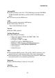
Introduction On-BoardIDE z An IDE controller on the VIA® VT82C686B chipset provides IDE HDD/ CD-ROM with PIO, Bus Master and Ultra DMA 33/66/100 operation modes. z Can connect up to four IDE devices Audio z Audio controller integrated in 686B chipset z SW Audio Codec VIA 1611A - Front Audio Pin Header onboard Network z Realtek 8100L (optional) On-Board Peripherals z On-Board Peripherals include: - 1 floppy port supports 2 FDDs with 360K, 720K, 1.2M, 1.44M and 2.88Mbytes.
Chapter 1 Mainboard Layout Top : mouse Bottom : keyboard SOCKET 370 ATX Power Supply CPUFAN DIMM 1 DIMM 2 Top : Parallel Port Bottom: COM Port & VGA Port COM 2 VT8601T Top : Game Port FDD IDE 2 BATT + IDE 1 PCI Slot 1 AUX_IN CD_IN MODEM_IN Bottom: Line-Out Line-In Mic PCI Slot 2 Codec VT82C 686B PCI Slot 3 JFP1 JBIOS WOL1 BIOS JMDM1 CNR USB2 SYSFAN JIR1 Front Audio ISA (Optional) MS-6368 (v5.
Introduction Quick Components Guide Component Function Reference DIMM 1~2 Installing memory modules See p. 2-4~2-5 Socket 370 Installing CPU See p. 2-2~2-3 CPUFAN Connecting to CPUFAN See p. 2-17 SYSFAN Connecting to SYSFAN See p. 2-17 ATX Power Supply Installing power supply See p. 2-6 IDE1& IDE2 Connecting to IDE hard disk drive See p.2-13 FDD Connecting to floppy disk drive See p.2-12 USB2 Connecting to USB interfaces See p.
Chapter 1 Key Features z z z z z z z z z z Micro-ATX Form Factor CPU: Socket 370 for Intel® CeleronTM/Pentium® III (including Tualatin)/ VIA C3™ Processor Memory: 2 SDRAM DIMMs Slot: 1 CNR slot, 3 PCI slots, 1 ISA slot (optional) I/O: 2 serial ports (COM2 is the onboard pin header), 1 parallel port, 4 USB ports, 1 floppy port, 1 IrDA connector, 1 Audio/Game port, 1 VGA port, 1 LAN jack (optional) LAN Wake up Function Modem (External/Internal) Ring Wake up Function Chip integrated audio PC 2001 compliant S
Hardware Setup Chapter 2. Hardware Setup 2 Hardware Setup This chapter provides you with the information about hardware setup procedures. While doing the installation, be careful in holding the components and follow the installation procedures. For some components, if you install in the wrong orientation, the components will not work properly. Use a grounded wrist strap before handling computer components. Static electricity may damage the components.
Chapter 2 Central Processing Unit: CPU The mainboard supports Intel® Celeron™, Pentium® III (including Tualatin) and VIA C3™ processor. The mainboard uses a CPU socket called Socket 370 for easy CPU installation. Make sure the CPU has a Heat Sink and a cooling fan attached on top to prevent overheating. If you do not find the Heat Sink and cooling fan, contact your dealer to purchase and install them before turning on the computer. CPU Installation Procedures Open Lever 1.
Hardware Setup CPU Core Speed Derivation Procedure The mainboard can automatically set the CPU Host Bus Frequency Clock. If CPU Clock Core/Bus ratio then CPU core speed WARNING! = = = = = 100MHz 7 Host Clock x Core/Bus ratio 100MHz x 7 700MHz Overclocking This motherboard is designed to support overclocking. However, please make sure your components are able to tolerate such abnormal setting, while doing overclocking. Any attempt to operate beyond product specifications is not recommended.
Chapter 2 Memory DIMM2 DIMM1 The mainboard supports a maximum memory size of 1GB. It provides two 168-pin unbuffered SDRAM DIMM (Double In-Line Memory Module) sockets and supports 64MB to 512MB technology. Introduction to SDRAM Synchronous DRAM (SDRAM) is a type of dynamic RAM memory chip that has been widely used starting in the latter part of the 1990s. SDRAMs are based on standard dynamic RAM chips, but have sophisticated features that make them considerably faster.
Hardware Setup DIMM Modules Combination At least one DIMM module should be installed on the motherboard. Memory modules can be installed on the slots in any order. The single-/ double-sided module each DIMM slot supports is listed below: Socket Memory Module Total Memory DIMM 1 (Bank0 & Bank1) S/D 64MB ~ 512MB DIMM 2 (Bank2 & Bank3) S/D 64MB ~ 512MB Maximum System Memory Supported S: Single Side 64MB ~ 1GB D: Double Side Installing DIMM Modules 1.
Chapter 2 Power Supply The mainboard supports ATX power supply for the power system. Before connecting to the power supply, always make sure that all components are installed properly and no damage will be caused. ATX 20-Pin Power Supply This connector allows you to connect to an ATX power supply. To connect to the ATX power supply, make sure the power supply connector is installed in the right orientation and the pins are aligned.
Hardware Setup Back Panel The Back Panel provides the following connectors: Mouse LAN Keyboard USB Parallel COM 1 Midi/Joystick VGA L-out L-in MIC Mouse Connector The mainboard provides a standard PS/2® mouse mini DIN connector for attaching a PS/2® mouse. You can plug a PS/2® mouse directly into this connector.
Chapter 2 Keyboard Connector The mainboard provides a standard PS/2® keyboard mini DIN connector for attaching a PS/2® keyboard. You can plug a PS/2® keyboard directly into this connector.
Hardware Setup Parallel Port Connector The mainboard provides a 25-pin female centronic connector for LPT. A parallel port is a standard printer port that supports Enhanced Parallel Port (EPP) and Extended Capabilities Parallel Port (ECP) mode.
Chapter 2 Serial Port Connector: COM 1 & COM 2 The mainboard has one 9-pin male DIN connector COM 1 and one 9-pin COM 2 pin header, which allows you to attach a serial port bracket. You can attach a serial mouse or other serial devices to serial ports.
Hardware Setup Joystick/Midi Connectors You can connect a joystick or game pad to this connector. Audio Port Connectors Line Out is to connect speakers or headphones. Line In is a connector for external CD player, Tape player or other audio devices. Mic is used to connect to a microphone. Line Out Line In MIC LAN Jack (RJ-45) (Optional) The mainboard provides one standard RJ-45 jack for connection to Local Area Network (LAN). You can connect a network cable to the LAN jack.
Chapter 2 Connectors The mainboard provides connectors to connect to FDD, IDE HDD, case, modem, LAN, USB Ports, IR module and CPU/System FAN. Floppy Disk Drive Connector: FDD The mainboard provides a standard floppy disk drive connector that supports 360K, 720K, 1.2M, 1.44M and 2.88M floppy disk types. 2 1 33 34 FDD USB Front Panel Connector: USB2 The mainboard provides one Front USB (Universal Serial Bus) pin header that allows you to connect optional USB ports for Front Panel.
Hardware Setup Hard Disk Connectors: IDE1 & IDE2 The mainboard uses an IDE controller on the VIA® VT82C686B chipset that provides PIO mode 0-4, Bus Master, and Ultra DMA 33/66/100 modes. It has two HDD connectors IDE1 (Primary) and IDE2 (Secondary). You can connect up to four hard disk drives, CD-ROM or 120MB Floppy to IDE1 and IDE2. IDE1 (Primary IDE Connector) - The first hard disk drive should always be connected to IDE1. You can connect a Master and a Slave drive to IDE1.
Chapter 2 Case Connector: JFP1 The case connector block JFP1 allows you to connect to the Power Switch, Reset Switch, Speaker, Power LED and HDD LED on the case. 14 7 Reset Switch + Speaker Power Switch Power LED 8 1 JFP1 HDD LED JFP1 Pin Definition Pin Description Pin Description 1 HDD+ 8 HDD- 2 SLED- 9 SPK- 3 PLED- 10 BUZ+ 4 PLED+ 11 BUZ- 5 PWSW+ 12 SPK+ 6 PWSW- 13 RST+ 7 NC 14 RST- Power Switch Connect to a 2-pin push button switch.
Hardware Setup Reset Switch Reset switch is used to reboot the system rather than turning the power ON/ OFF. Avoid rebooting while the HDD is working. You can connect the Reset switch from the system case to this pin. Power LED The Power LED is lit while the system power is on. Speaker Speaker from the system case is connected to this pin. HDDLED HDD LED shows the activity of a hard disk drive. Avoid turning the power off while the HDD is working.
Chapter 2 Wake On Ring Connector: JMDM1 This connector allows you to connect to a modem card with Wake On Ring function. The connector will power up the system when a signal is received through the modem card. MDM_WAKEUP 5VSB NC GND 1 JMDM1 Wake On LAN Connector: WOL1 This connector allows you to connect to a LAN card with Wake On LAN function. You can wake up the computer via remote control through a local area network.
Hardware Setup Fan Power Connectors: CPUFAN/SYSFAN The CPUFAN (processor fan) and SYSFAN (system fan) support system cooling fan with +12V. It supports three-pin head connector. When connecting the wire to the connectors, always take note that the red wire is the positive and should be connected to the +12V, the black wire is Ground and should be connected to GND.
Chapter 2 CD-In/Aux Line-In/Modem-In Connector: CD_IN/AUX_IN/ MODEM_IN CD_IN connector is for CD-ROM audio connector. AUX_IN connector is for DVD add-on card with Line-in connector. MODEM_IN connector is for modem with internal audio connector. Mono_Out GND Phone_In R R GND GND L L CD_IN MODEM_IN AUX_IN Note: Mono_Out is connected to the Modem speaker-out connector. Phone_In is connected to the Modem Microphone-In connector.
Hardware Setup IrDA Infrared Module Connector: JIR1 This connector allows you to connect an IrDA Infrared module. You must configure the setting through the BIOS setup to use the IR function.
Chapter 2 Front Panel Audio Connector: FRONT AUDIO You can connect an optional audio connector to the Front Panel Audio Header.
Hardware Setup Note: To have the Line-out connector on the back panel work properly, you need to place the jumper on the pin# 11~14 of the FRONT AUDIO connector. Otherwise, this Line-out connector will not function and nothing can be heard through speakers or headphones attached to the connector. But front panel audio connector is enabled at this point and allows you to connect speakers or headphones.
Chapter 2 Jumpers The motherboard provides the following jumpers for you to set the computer’s function. This section describes how to change your motherboard’s function through the use of jumpers. Clear CMOS Jumper: JBIOS There is a CMOS RAM on board that has a power supply from external battery to keep the data of system configuration. With the CMOS RAM, the system can automatically boot OS every time it is turned on.
Hardware Setup BIOS Flash Jumper: JBIOS1 This jumper is used to lock or unlock the boot block area on BIOS. When unlocked, the BIOS boot block area can be updated. When locked, the BIOS boot block area can not be updated.
Chapter 2 Slots The motherboard provides three 32-bit Master PCI Bus Slots, one CNR and one optional ISA slot. PCI Slots CNR Slot ISA Slot (Optional) PCI Slots Three PCI slots allow you to install expansion cards to meet your needs. When adding or removing expansion cards, make sure that you unplug the power supply first. Meanwhile, read the documentation for the expansion card to make any necessary hardware or software settings for the expansion card, such as jumpers, switches or BIOS configuration.
Hardware Setup PCI Interrupt Request Routing The IRQ, abbreviation of interrupt request line and pronounced I-R-Q, are hardware lines over which devices can send interrupt signals to the microprocessor.
AWARD® BIOS Setup Chapter 3. AWARD ® B I O S Setup ® BIOS Setup AWARD 3 The mainboard uses AWARD® BIOS ROM that provides a Setup utility for users to modify the basic system configuration. The information is stored in a battery-backed CMOS RAM so it retains the Setup information when the power is turned off.
Chapter 3 Entering Setup Power on the computer and the system will start POST (Power On Self Test) process. When the message below appears on the screen, press key to enter Setup. Hit DEL if you want to run SETUP If the message disappears before you respond and you still wish to enter Setup, restart the system by turning it OFF and On or pressing the RESET button. You may also restart the system by simultaneously pressing , , and keys.
AWARD® BIOS Setup Getting Help After entering the Setup utility, the first screen you see is the Main Menu. Main Menu The main menu displays the setup categories the BIOS supplies. You can use the arrow keys ( ↑↓ ) to select the item. The on-line description for the selected setup category is displayed on the bottom of the screen.
Chapter 3 The Main Menu Once you enter AWARD® BIOS CMOS Setup Utility, the Main Menu will appear on the screen. The Main Menu displays eleven configurable functions and two exit choices. Use arrow keys to move among the items and press to enter the sub-menu. Standard CMOS Features Use this menu for basic system configurations, such as time, date etc. Advanced BIOS Features Use this menu to setup the items of Award® special enhanced features.
AWARD® BIOS Setup PnP/PCI Configurations This entry appears if your system supports PnP/PCI. PC Health Status This entry displays the current status of your PC. Frequency/Voltage Control Use this menu to specify your settings for frequency/voltage control. Load Fail-Safe Defaults Use this menu to load the BIOS default values for the minimal/stable performance of your PC. Load Optimized Defaults Use this menu to load the default factory settings for BIOS for optimal system performance.
Chapter 3 Standard CMOS Features The items inside Standard CMOS Features menu are divided into 13 categories. Each category includes none, one or more setup items. Use the arrow keys to highlight the item you want to modify and use the or keys to switch to the value you prefer. Date This allows you to set the system to the date that you want (usually the current date). The format is . day Day of the week, from Sun to Sat, determined by BIOS. Read-only.
AWARD® BIOS Setup IDE Primary Master/Primary Slave/Secondary Master/Secondary Slave Press PgUp/<+> or PgDn/<-> to select the hard disk drive type. The specification of hard disk drive will show up on the right hand according to your selection. Access Mode Capacity Cylinder Head Precomp Landing Zone Sector The settings are Auto, CHS, LBA and Large. The formatted size of the storage device. Number of cylinders. Number of heads. Write precompensation. Cylinder location of the landing zone.
Chapter 3 boot. Available options are: All Errors No Errors All, But Keyboard All, But Diskette All, But Disk/Key The system stops when any error is detected. The system doesn’t stop for any detected error. The system doesn’t stop for a keyboard error. The system doesn’t stop for a disk error. The system doesn’t stop for either a disk or a keyboard error.
AWARD® BIOS Setup Advanced BIOS Features Anti-Virus Protection The item is to set the Virus Warning feature for IDE Hard Disk boot sector protection. If the function is enabled and any attempt to write data into this area is made, BIOS will display a warning message on screen and beep. Settings: Disabled and Enabled. CPU Internal/External Cache Cache memory is additional memory that is must faster than conventional DRAM (system memory).
Chapter 3 for error detection and correction when data passes through L2 cache memory. Settings: Enabled and Disabled. Processor Number Feature This feature is for Pentium® !!! only. When set to Enabled, the system will check CPU Serial Number. Set to Disabled if you don’t want the system to know the CPU Serial Number. Quick Power On Self Test Setting the item to Enabled allows the system to shorten boot time since it will skip some check items. Settings: Enabled and Disabled.
AWARD® BIOS Setup process: the drive activity light will come on and the head will move back and forth once. Settings: Enabled and Disabled. Boot Up NumLock Status This item is to set the Num Lock status when the system is powered on. Setting to On will turn on the Num Lock key when the system is powered on. Setting to Off will allow end users to use the arrow keys on the numeric keypad. Settings: On and Off. Gate A20 Option This item is to set the Gate A20 status.
Chapter 3 Option Setup System Description The password prompt appears only when end users try to run Setup. A password prompt appears every time when the computer is powered on or when end users try to run Setup. APICMode This field is used to enable or disable the APIC (Advanced Programmable Interrupt Controller). Due to compliance to PC2001 design guide, the system is able to run in APIC mode. Enabling APIC mode will expand available IRQs resources for the system. Settings: Enabled and Disabled.
AWARD® BIOS Setup Advanced Chipset Features Note: Change these settings only if you are familiar with the chipset. DRAM Timing By SPD Selects whether DRAM timing is configured by reading the contents of the SPD (Serial Presence Detect) device on the DRAM module. Setting to Enabled makes both SDRAM Cycle Length and DRAM Clock automatically determined by BIOS according to the configurations on the SPD.
Chapter 3 HCLK-33M The DRAM clock will be equal to the Host Clock minus 33MHz. For example, if the Host Clock is 133MHz, the DRAM clock will be 100MHz. HCLK+33M The DRAM clock will be equal to the Host Clock plus 33MHz. For example, if the Host Clock is 100MHz, the DRAM clock will be 133MHz. Memory Hole In order to improve performance, certain space in memory can be reserved for ISA cards. This memory must be mapped into the memory space below 16MB. When this area is reserved, it cannot be cached.
AWARD® BIOS Setup Frame Buffer Size Frame Buffer is the video memory that stores data for video display (frame). This field is used to determine the memory size for Frame Buffer. Larger frame buffer size increases video performance. Settings: 2M, 4M and 8M. AGP Aperture Size Selects the size of the Accelerated Graphics Port (AGP) aperture. Aperture is a portion of the PCI memory address range dedicated for graphics memory address space.
Chapter 3 PCI Dynamic Bursting When Enabled, every write transaction goes to the write buffer. Then burstable transactions burst on the PCI bus and nonburstable transactions do not. PCI Master 0 WS Write When Enabled, writes to the PCI bus are executed with zero wait state.
AWARD® BIOS Setup Integrated Peripherals OnChip IDE Channel0/1 The integrated peripheral controller contains an IDE interface with support for two IDE channels. Choose Enabled to activate each channel separately. IDE Prefetch Mode The onboard IDE drive interfaces supports prefetching, for faster drive accesses. Set to Disabled if your primary and/or secondary add-in IDE interface does not support prefetching.
Chapter 3 cally determines the best mode for each IDE device. Primary/Secondary Master/Slave UDMA Ultra DMA implementation is possible only if your IDE device supports it and your operating environment contains a DMA driver. If both your hard drive and software support Ultra DMA, select Auto to enable BIOS support. Init Display First This item specifies which VGA card is your primary graphics adapter. Available options: PCI Slot and AGP.
AWARD® BIOS Setup Default is Auto.
Chapter 3 TX, RX inverting enable This item allows you to enable the TX, RX inverting which depends on different H/W requirement. This field is not recommended to change its default setting for avoiding any error in your system. Settings are “No, Yes”, “Yes, No”, “Yes, Yes” and “No, No.” Onboard Parallel Port This specifies the base I/O port address and IRQ of the onboard Parallel Port. Settings: 378/IRQ7, 278/IRQ5, 3BC/IRQ7 and Disabled.
AWARD® BIOS Setup Parallel Port EPP Type The item selects the EPP version used by the parallel port if the port is set to EPP or ECP/EPP mode. Settings: EPP1.7 and EPP1.9. Onboard Legacy Audio The item enables or disables the onboard audio features of the mainbaord and the following audio options in the BIOS. Sound Blaster The item turns on/off the Sound Blaster feature of the board. If you want to play the Sound Blaster compatible games, you need to set the field to Enabled.
Chapter 3 Power Management Setup ACPI function This item is to activate the ACPI (Advanced Configuration and Power Management Interface) Function. If your operating system is ACPI-aware, such as Windows 98SE/2000/ME, select Enabled. Settings: Enabled and Disabled. Power Management Press to enter the sub-menu for power management options.
AWARD® BIOS Setup Power Management This item is used to select the degree (or type) or power saving and is related to these modes: Doze Mode and Suspend Mode. There are three options for power management: Min Saving Minimum Power Management. Doze Mode = 1 Hour, Suspend Mode = 1 Hour. Max Saving Maximum Power Management. Doze Mode = 10 Sec, Suspend Mode = 10 Sec. User Define Allows end users to configure each mode separately. Each of the ranges are from 1 Min to 1 Hour.
Chapter 3 S3(STR) ware maintains all system context. The S3 sleep mode is a power-down state in which power is supplied only to essential components such as main memory and wake-capable devices, and all system context is saved to main memory. The information stored in main memory will be used to restore PC to previous state when an “wake up” event occurs. PM Control by APM Setting to Yes will activate an Advanced Power Management (APM) device to enhance Max Saving mode and stop CPU internal clock.
AWARD® BIOS Setup Soft-Off by PWRBTN This feature allows users to configure the power button as a normal poweron/-off button or a soft-off button. Settings are: Instant-Off The power button functions as a normal power-on/off button. Delay 4 Sec. When you press the power button, the computer enters the suspend/sleep mode, but if the button is pressed for more than four seconds, the computer is turned off.
Chapter 3 VGA, LPT & COM, HDD & FDD, PCI Master, PowerOn by PCI Card, Wake Up On LAN/Ring These items specify whether the system will be awakened from power saving modes when activity or input signal of the specified hardware peripheral or component is detected. Note: To use the function of “Wake Up On LAN/Ring”, you need to install a modem/LAN card supporting power on function. RTC Alarm Resume This is to enable or disable the feature of booting up the system on a scheduled time/date.
AWARD® BIOS Setup Primary INTR When this is set to ON, any event occurring will wake up the system which has been powered down. IRQ3~IRQ15 Enables or disables the monitoring of the specified IRQ line. If set to Enabled, the activity of the specified IRQ line will prevent the system from entering power saving modes or awaken it from power saving modes. Note: IRQ (Interrupt Request) lines are system resources allocated to I/O devices.
Chapter 3 PnP/PCI Configurations PNP OS Installed When set to YES, BIOS will only initialize the PnP cards used for booting (VGA, IDE, SCSI). The rest of the cards will be initialized by the PnP operating system like Windows® 95 or 98. When set to NO, BIOS will initialize all the PnP cards. So, select Yes if the operating system is Plug & Play aware.
AWARD® BIOS Setup Manual. Press and you will enter the sub-menu of the items. IRQ Resources & DMA Resources list IRQ-3/-4/-5/-7/-9/-10/-11/-12/-14/-15 and DMA-0/-1/-3/-5/-6/-7 for users to set each IRQ/DMA a type depending on the type of device using the IRQ/DMA. Settings are: PCI/ISA PnP For Plug & Play compatible devices designed for PCI or ISA bus architecture. Legacy ISA For devices compliant with the PC AT bus specification, requiring a specific interrupt.
Chapter 3 PC Health Status This section is to monitor the current hardware status including CPU temperature, CPU Fan speed, Vcore etc. This is available only if there is hardware monitoring onboard. Current CPU Temp., Current System Temp., Current CPU/System Fan Speed, Vcore, 2.5/3.3/5/12V These items display the current status of all of the monitored hardware devices/components such as CPU voltages, temperatures and all fans’s speed.
AWARD® BIOS Setup Frequency/Voltage Control Auto Detect DIMM/PCI Clk This item is used to auto detect the DIMM/PCI slots. When set to Enabled, the system will remove (turn off) clocks from empty DIMM/PCI slots to minimize the electromagnetic interference (EMI). Settings: Enabled and Disabled. Spread Spectrum When the motherboard clock generator pulses, the extreme values (spikes) of the pulses creates EMI (Electromagnetic Interference).
Chapter 3 Load Fail-Safe/Optimized Defaults The two options on the main menu allow users to restore all of the BIOS settings to the default Fail-Safe or Optimized values. The Optimized Defaults are the default values set by the mainboard manufacturer specifically for the optimal performance of the mainboard. The Fail-Safe Defaults are the default values set by the BIOS vendor for the stable system performance.
AWARD® BIOS Setup When you select Load Optimized Defaults, a message as below appears: Pressing Y loads the default factory settings for optimal system performance.
Chapter 3 Set Supervisor/User Password When you select this function, a message as below will appear on the screen: Type the password, up to eight characters in length, and press . The password typed now will clear any previously set password from CMOS memory. You will be prompted to confirm the password. Re-type the password and press . You may also press to abort the selection and not enter a password.
AWARD® BIOS Setup enter Setup. About Supervisor Password & User Password: Supervisor password : Can enter and change the settings of the setup menu. Can only enter but do not have the right to change the settings of the setup menu.
Chapter 3 Save & Exit Setup When you want to quit the Setup menu, you can select this option to save the changes and quit. A message as below will appear on the screen: Typing Y will allow you to quit the Setup Utility and save the user setup changes to RTC CMOS. Typing N will return to the Setup Utility.
AWARD® BIOS Setup Exit Without Saving When you want to quit the Setup menu, you can select this option to abandon the changes. A message as below will appear on the screen: Typing Y will allow you to quit the Setup Utility without saving any changes to RTC CMOS. Typing N will return to the Setup Utility.
Installing Drivers Chapter 4. Installing Drivers 4 Installing Drivers The chapter describes how to install drivers for VIA chipset, AC97 audio, VGA and Realtek® 8100 fast ethernet controller, and the basic system requirements for driver installation. To install the drivers correctly, you must install VIA chipset driver prior to other drivers. This chapter includes the following topics: VIA Driver Installation for Windows® 98SE/ 2000/ME/NT4.
Chapter 4 VIA Driver Installation for Windows® 98SE/2000/ ME/NT4.0 Note 1: Install Windows® 2000 Service Pack2 or the latest version before installing the VIA drivers into Windows® 2000. Note 2: Install Windows® NT4.0 Service Pack 6 or above before installing the VIA drivers into Windows® NT. Installing VIA® Chipset Driver 1. Insert the supplied CD disk into the CD-ROM drive. 2. The CD will auto-run and the setup screen will appear. 3.
Installing Drivers One Touch Setup: In Windows 2000/ME, you may see the One Touch Setup button appear on the setup screen. Choosing the button will help you to install more than one driver into the system without going through the installation process step by step and save a lot of time accordingly. After clicking on One Touch Setup, a window will show up indicating what drivers will be installed. Install other drivers not included by One Touch Setup manually if any.
Chapter 4 Realtek® 8100L Fast Ethernet Controller When your mainboard comes with the Realtek® 8100L LAN controller, you must install the Realtek® LAN driver to support the LAN function. The Realtek® 8100L is a sophisticated 32-bit PCI component, with enhanced scatter-gather bus mastering capabilities. Its true 32-bit architecture enables it to perform high speed data transfers on the PCI bus using four DMA channels. Features IEEE 802.3/802.
Installing Drivers Installation for Windows® NT4.0 1. Insert the supplied CD disk into the CD-ROM drive. 2. Copy all files under CD-ROM drive:\Network\Realtek\8139\Winnt4 to your hard disk. For example, copy the files to C:\Lan. 3. Right click on Network Neighborhood. 4. Select Properties. 5. Click Yes to install the driver. 6. Click Next. 7. Choose Select from list. 8. Click Have Disk to specify the path of Lan driver. 9. Type the path where the Lan driver exists.