MS-6390 (v3.
Manual Rev: 3.0 Release Date: February 2004 FCC-B Radio Frequency Interference Statement This equipment has been tested and found to comply with the limits for a class B digital device, pursuant to part 15 of the FCC rules. These limits are designed to provide reasonable protection against harmful interference when the equipment is operated in a commercial environment.
Copyright Notice The material in this document is the intellectual property of MICRO-STAR INTERNATIONAL. We take every care in the preparation of this document, but no guarantee is given as to the correctness of its contents. Our products are under continual improvement and we reserve the right to make changes without notice. Trademarks All trademarks are the properties of their respective owners. AMD, Athlon™, Athlon™ XP, Thoroughbred™, and Duron™ are registered trademarks of AMD Corporation.
Safety Instructions 1. 2. 3. 4. 5. Always read the safety instructions carefully. Keep this User’s Manual for future reference. Keep this equipment away from humidity. Lay this equipment on a reliable flat surface before setting it up. The openings on the enclosure are for air convection hence protects the equipment from overheating. DO NOT COVER THE OPENINGS. 6. Make sure the voltage of the power source and adjust properly 110/220V before connecting the equipment to the power inlet. 7.
CONTENTS FCC-B Radio Frequency Interference Statement ............................................ ii Copyright Notice ........................................................................................... iii Trademarks .................................................................................................... iii Revision History ........................................................................................... iii Technical Support ..................................................
Parallel Port Connector: LPT1 ...................................................... 2-13 Audio Port Connectors ............................................................... 2-14 Connectors ......................................................................................... 2-15 Floppy Disk Drive Connector: FDD1 ............................................ 2-15 Internal Speaker Connector: JSP1 ................................................ 2-15 Hard Disk Connectors: IDE1 & IDE2 ....................
Getting Started Chapter 1. Getting Started Getting Started Thank you for purchasing the MS-6390 v3.X Micro ATX mainboard. The MS-6390 is based on VIA® KM266 & VT8235 chipsets for optimal system efficiency. Designed to fit the advanced AMD® Athlon™, Athlon™ XP or Duron™ processors, the MS-6390 delivers a high performance and professional desktop platform solution.
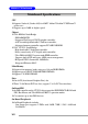
6390 M-ATX Mainboard MS-6390 M-ATX Mainboard Mainboard Specifications CPU h Supports Socket A (Socket-462) for AMD® Athlon™/Athlon™ XP/Duron™ processors. h Supports up to 2600+ or higher speed. Chipset h VIA® KM266 North Bridge - 200/266MHz FSB. - Integrated ProSavage8 2D/3D graphic controller. - AGP 4x and high bandwidth V-link host controller. - Advanced memory controller supports PC1600/2100 DDR. h VIA® VT8235 South Bridge - High bandwidth V-link client controller.
Getting Started - One serial port (COM A) - One VGA port - One parallel port supports SPP/EPP/ECP mode - One RJ-45 LAN port - Vertical audio ports - One 3-pin internal speaker connector - Six USB 2.0 ports (Rear * 4/ Front * 2) Audio h 5.1 channel AC’97 software audio integrated on VT8235 south bridge. h RealTek ALC650 6-channel audio. LAN h VIA® VT8235 integrated MAC + VT6103 PHY.
6390 M-ATX Mainboard MS-6390 M-ATX Mainboard Mainboard Layout Top: Mouse Bottom: Keyboard CONN1 JPW1 SOCKET 462 USB Ports Winbond 83697HF BIOS CPUFA1 FDD1 Top: LPT Bottom: COM A VGA Port VIA KM266 T: RJ45 LAN Jack B: USB Ports SYSFA1 Line-In Line-Out Mic IDE 1 IDE 2 DIMM1 PCI Slot 1 DIMM2 AGP Slot VIA VT6103 JSP1 PCI Slot 2 VT8235 Codec JBAT1 JCD1 BATT + JFMIC JAUX1 JFP1 JUSB1 MS-6390 v3.
Hardware Setup Chapter 2. Hardware Setup Hardware Setup This chapter provides you with the information about hardware setup procedures. While doing the installation, be careful in holding the components and follow the installation procedures. For some components, if you install in the wrong orientation, the components will not work properly. Use a grounded wrist strap before handling computer components. Static electricity may damage the components.
MS-6390 M-ATX Mainboard 6390 M-ATX Mainboard Quick Components Guide CPU, p.2-3 CONN1, p.2-9 CPUFA1, p.2-17 DIMM1/2, p.2-7 JPW1, p.2-9 Back Panel I/O, p.2-10 FDD1, p.2-15 SYSFA1, p.2-17 AGP Slot, p.2-24 JSP1, p.2-15 JCD1, p.2-18 JAUX1, p.2-18 IDE1/2, p.2-16 PCI Slots, p.2-24 JPWD1, p.2-23 JBAT1, p.2-21 SW1, p.2-22 JFP1, p.2-19 JFMIC, p.2-18 JUSB1, p.
Hardware Setup Central Processing Unit: CPU The mainboard supports AMD® Athlon™, Athlon™ XP and Duron™ processors in the 462 pin package. The mainboard uses a CPU socket called Socket A for easy CPU installation. When you are installing the CPU, make sure the CPU has a heat sink and a cooling fan attached on the top to prevent overheating. If you do not find the heat sink and cooling fan, contact your dealer to purchase and install them before turning on the computer.
MS-6390 M-ATX Mainboard 6390 M-ATX Mainboard CPU Installation Procedures for Socket 462 1. Please turn off the power and unplug the power cord before installing the CPU. Open Lever Sliding Plate 90 degree 2. Pull the lever sideways away from the socket. Make sure to raise the lever up to a 90degree angle. Gold arrow 3. Look for the gold arrow. The gold arrow should point towards the lever pivot. The CPU can only fit in the correct orientation. 4.
Hardware Setup Installing AMD Athlon CPU (Socket 462) Cooler Set The following instructions will guide you through the heat sink installation procedures. Please consult your agent for the proper CPU cooler set. 1. Position your CPU cooler set onto the CPU. Apply some heat sink paste 2. Use one end of the clip to hook the latch of the CPU sliding plate. 3. Hook the other latch to fix the cooling fan set. You may need a screw drive to press down the other side of the clip. 4.
MS-6390 M-ATX Mainboard 6390 M-ATX Mainboard Setting CPU Clock Frequency through Jumper The hardware configuration for CPU clock frequency of the motherboard is set to 133MHz by default. Therefore, to make a 100MHz CPU run at 100MHz when it is installed on the board, you have to adjust the CPU clock frequency through jumper. To set the clock frequency of the installed CPU, refer to Jumpers/FSB Clock Jumper: SW1 in later section of this chapter.
Hardware Setup Memory The mainboard provides 2 slots for 184-pin DDR SDRAM DIMM (Double In-Line Memory Module) modules and supports the memory size up to 2GB. You can install PC2100/DDR266 or PC1600/DDR200 modules on the DDR DIMM slots (DIMM 1~2). DDR DIMM Slots (DIMM 1~2) Introduction to DDR SDRAM DDR (Double Data Rate) SDRAM is similar to conventional SDRAM, but doubles the rate by transferring data twice per cycle. It uses 2.5 volts as opposed to 3.
MS-6390 M-ATX Mainboard 6390 M-ATX Mainboard DIMM Module Combination Install at least one DIMM module on the slots. Memory modules can be installed on the slots in any order. You can install either single- or double-sided modules to meet your own needs.
Hardware Setup Power Supply The mainboard supports ATX power supply for the power system. Before inserting the power supply connector, always make sure that all components are installed properly to ensure that no damage will be caused. ATX 20-Pin Power Connector: CONN1 This connector allows you to connect to an ATX power supply. To connect to the ATX power supply, make sure the plug of the power supply is inserted in the proper orientation and the pins are aligned.
MS-6390 M-ATX Mainboard 6390 M-ATX Mainboard Back Panel The back panel provides the following connectors: Parallel Mouse LAN L-In L-Out MIC Keyboard USB COM A VGA USB Mouse/Keyboard Connector The mainboard provides a standard PS/2® mouse/keyboard mini DIN connector for attaching a PS/2® mouse/keyboard. You can plug a PS/2® mouse/ keyboard directly into this connector.
Hardware Setup USB Connectors The mainboard provides four UHCI (Universal Host Controller Interface) Universal Serial Bus roots for attaching USB devices such as keyboard, mouse or other USB-compatible devices. You can plug USB devices directly into the connectors.
MS-6390 M-ATX Mainboard 6390 M-ATX Mainboard Serial Port Connector: COM A The mainboard provides one 9-pin serial port connector COM A. This port is a 16550A high speed communication port that sends/receives 16 bytes FIFOs. You can attach a serial mouse or other serial devices directly to the connector.
Hardware Setup Parallel Port Connector: LPT1 The mainboard provides a 25-pin female centronic connector as LPT. A parallel port is a standard printer port that supports Enhanced Parallel Port (EPP) and Extended Capabilities Parallel Port (ECP) mode.
MS-6390 M-ATX Mainboard 6390 M-ATX Mainboard Audio Port Connectors Line Out is a connector for Speakers or Headphones. Line In is used for external CD player, Tape player, or other audio devices. Mic is a connector for microphones.
Hardware Setup Connectors The mainboard provides connectors to connect to FDD, IDE HDD, case, modem, LAN, USB Ports, IR module and CPU/System/Power Supply FAN. Floppy Disk Drive Connector: FDD1 The mainboard provides a standard floppy disk drive connector that supports 360K, 720K, 1.2M, 1.44M and 2.88M floppy disk types. FDD1 Internal Speaker Connector: JSP1 This connector is used to connect the internal speaker if available.
MS-6390 M-ATX Mainboard 6390 M-ATX Mainboard Hard Disk Connectors: IDE1 & IDE2 IDE2 IDE1 The mainboard has a 32-bit Enhanced PCI IDE and Ultra ATA 66/100 controller that provides PIO mode 0~4, Bus Master, and Ultra ATA 66/100 function. You can connect up to four hard disk drives, CD-ROM, 120MB Floppy (reserved for future BIOS) and other devices. IDE1 (Primary IDE Connector) The first hard drive should always be connected to IDE1. IDE1 can connect a Master and a Slave drive.
Hardware Setup Fan Power Connectors: CPUFA1/SYSFA1 The CPUFA1 (processor fan) and SYSFA1 (system fan) support system cooling fan with +12V. It supports three-pin head connector. When connecting the wire to the connectors, always take note that the red wire is the positive and should be connected to the +12V, the black wire is Ground and should be connected to GND. SENSOR +12V GND CPUFA1 SENSOR +12V GND SYSFA1 NOTE: Always consult the vendors for proper CPU cooling fan.
MS-6390 M-ATX Mainboard 6390 M-ATX Mainboard CD-In Connector: JCD1 The connector is for CD-ROM audio connector. Aux Line-In Connector: JAUX1 The connector is for DVD add-on card with Line-in connector. Front Microphone Connector: JFMIC This connector is used to connect the front panel microphone if available.
Hardware Setup Front Panel Connector: JFP1 The mainboard provides one front panel connector for electrical connection to the front panel switches and LEDs. The JFP1 is compliant with Intel® Front Panel I/O Connectivity Design Guide.
MS-6390 M-ATX Mainboard 6390 M-ATX Mainboard Front USB Connector: JUSB1 The mainboard provides one USB 2.0 pin header JUSB1 (optional USB 2. 0 bracket available) that is compliant with Intel® I/O Connectivity Design Guide. USB 2.0 technology increases data transfer rate up to a maximum throughput of 480Mbps, which is 40 times faster than USB 1.1, and is ideal for connecting high-speed USB interface peripherals such as USB HDD, digital cameras, MP3 players, printers, modems and the like.
Hardware Setup Jumpers The motherboard provides the following jumpers for you to set the computer’s function. This section will explain how to change your motherboard’s function through the use of jumpers. Clear CMOS Jumper: JBAT1 There is a CMOS RAM on board that has a power supply from external battery to keep the data of system configuration. With the CMOS RAM, the system can automatically boot OS every time it is turned on.
MS-6390 M-ATX Mainboard 6390 M-ATX Mainboard FSB Clock Jumper: SW1 These two jumpers provide 100MHz and 133MHz Front Side Bus frequency selection for overclocking purpose.
Hardware Setup Clear BIOS Password Jumper: JPWD1 The jumper is used to clear the BIOS password. To clear the password, open the jumper and restart your computer.
MS-6390 M-ATX Mainboard 6390 M-ATX Mainboard Slots The motherboard provides one AGP slot and three 32-bit Master PCI bus slots. AGP Slot PCI Slots AGP (Accelerated Graphics Port) Slot The AGP slot allows you to insert the AGP graphics card. AGP is an interface specification designed for the throughput demands of 3D graphics. It introduces a 66MHz, 32-bit channel for the graphics controller to directly access main memory.
Hardware Setup PCI Interrupt Request Routing The IRQ, acronym of interrupt request line and pronounced I-R-Q, are hardware lines over which devices can send interrupt signals to the microprocessor.
BIOS Setup Chapter 3. BIOS Setup BIOS Setup This chapter provides information on the BIOS Setup program and allows you to configure the system for optimum use. You may need to run the Setup program when: An error message appears on the screen during the system booting up, and requests you to run SETUP. You want to change the default settings for customized features.
6390 M-ATX Mainboard Entering Setup Power on the computer and the system will start POST (Power On Self Test) process. Press to enter the BIOS Setup. If you fail to press and the system enters to the Windows OS and you still wish to enter Setup, restart the system by turning it OFF and On or pressing the RESET button. You may also restart the system by simultaneously pressing , , and keys.
BIOS Setup Getting Help After entering the Setup menu, the first menu you will see is the Main Menu. Main Menu The main menu lists the setup functions you can make changes to. You can use the arrow keys ( ↑↓ ) to select the item. The on-line description of the highlighted setup function is displayed at the bottom of the screen. Sub-Menu If you find a right pointer symbol (as shown in the right view) appears to the left of certain fields that means a submenu can be launched from this field.
6390 M-ATX Mainboard Main Once you enter Phoenix-Award® BIOS CMOS Setup Utility, the Main menu will appear on the screen. The Main menu allows you to select some basic information about the system. Use arrow keys to select among the items and press to accept or enter the sub-menu. System Date This allows you to set the system to the date that you want (usually the current date). The format is . day Day of the week, from Sun to Sat, determined by BIOS. Read-only.
BIOS Setup Floppy Diskette A This item allows you to set the type of floppy drives installed. Available options: Disabled, 720K, 3.5 in., 1.44M, 3.5 in., 2.88M, 3.5 in. Primary/Secondary Master/Slave Press PgUp/<+> or PgDn/<-> to select Manual, None or Auto type. Note that the specifications of your drive must match with the drive table. The hard disk will not work properly if you enter improper information for this category.
6390 M-ATX Mainboard Advanced CPU Type / CPU Speed / CPU Cache RAM These items show the related information of CPU. (read-only) Plug and Play Aware O/S When set to Yes, BIOS will only initialize the PnP cards used for booting (VGA, IDE, SCSI). The rest of the cards will be initialized by the PnP operating system like Windows 98, 2000 or ME. When set to No, BIOS will initialize all the PnP cards. Select Yes if the operating system is Plug & Play. Reset ESCD Normally, you leave this field No.
BIOS Setup PS/2 Mouse If your system has a PS/2 mouse port and you install a serial pointing device, select Disabled. Setting options: Auto Detected, Disabled, Enabled. Local Bus IDE Adapter The chipset contains a PCI IDE interface with support for two IDE channels. Select Primary to activate the only primary IDE interface, if you install an addin secondary interface.
6390 M-ATX Mainboard I/O device Configuration Press to enter the sub-menu screen. Serial Port Setting to Enabled to use the serial port. Setting options: Enabled, Disabled. Base Address/Interrupt This item is to select an address and corresponding address/interrupt for the first and second serial ports, and it is available only when Serial Port is set to Enabled. The settings are: 3F8/IRQ4, 2E8/ IRQ3, 3E8/IRQ4, 2F8/IRQ3, Disabled, Auto. Parallel Port Setting to Enabled to use the parallel port.
BIOS Setup On-Board Audio Options Press to enter the sub-menu screen. Codec This item is used to enable or disable the onboard AC’97 (Audio Codec’97) feature. Selecting Auto allows the mainboard to detect whether an audio device is used. If an audio device is detected, the onboard AC’97 controller will be enabled; if not, the controller is disabled. Disable the function if you want to use other controller cards to connect an audio device. Settings: Enabled, Disabled and Auto.
6390 M-ATX Mainboard Power After AC Power Failure This setting specifies whether your system will reboot after a power failure or interrupt occurs. Available settings are: Stay Off Leaves the computer in the power off state. Power On Leaves the computer in the power on state. Auto Restores the system to the previous status before power failure or interrupt occurred.
BIOS Setup Boot Quick Boot Mode Setting the item to Enabled allows the system to boot within 5 seconds since it will skip some check items. Available options: Enabled, Disabled. Boot Device Priority Press to enter the sub-menu and the following screen appears: Boot Device Priority: 1st/2nd/3rd/4th The items allow you to set the sequence of boot devices where BIOS attempts to load the disk operating system.
6390 M-ATX Mainboard MSI Reminds You... Available settings for “1st/2nd/3rd/4th Boot Device” vary depending on the bootable devices you have installed. For example, if you did not install a floppy drive, the setting “Floppy” does not show up. Hark Disk Boot Priority Press to enter the sub-menu and the following screen appears: Here it shows the bootable add-in cards like IDE cards and SCSI cards... etc. Read-only.
BIOS Setup Exit Exit Saving Changes / Exit Discarding Changes / Load Setup Default / Discard Changes / Save Changes You may choose one of these options before leaving the BIOS setup utility. Exit Saving Change Exit System Setup utility and saves your changes to CMOS. Exit Discarding Changes Exit System Setup utility without saving setup data to CMOS. Load Setup Default Load the default values for all the setup items. Discard Changes Load previous values from CMOS for all setup items.