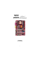
MSI 845 Ultra-C MS-6566 (v1.X) ATX Mainboard Version 1.
ManualRev: 1.0 Release Date: Dec. 2001 FCC-B Radio Frequency Interference Statement This equipment has been tested and found to comply with the limits for a class B digital device, pursuant to part 15 of the FCC rules. These limits are designed to provide reasonable protection against harmful interference when the equipment is operated in a commercial environment.
Edition Dec. 2001 Copyright Notice The material in this document is the intellectual property of MICRO-STAR INTERNATIONAL. We take every care in the preparation of this document, but no guarantee is given as to the correctness of its con tents. Our products are under co ntinual improvement and we reserve the right to make changes without notice. Trademarks All trademarks are the properties of their respective owners. Intel® and Pentium® are registered trademarks of Intel Corporation.
Safety Instructions 1. 2. 3. 4. 5. Read the safety instructions carefully. Save this User’s Guide for possible use later. Keep this equipment away from humidity. Lay this equipment on a stable and flat surface before setting it up. The openings on the enclosure are used for air convection and to prevent the equipment from overheating. Note: Do not cover the openings. 6.
CONTENTS Chapter 1. Getting Started ................................................................................ 1-1 Mainboard Specification .............................................................................. 1-2 Mainboard Layout ........................................................................................ 1-4 Quick Components Guide ............................................................................ 1-5 MSI Special Features .................................................
Audio Port Connectors ...................................................................... 2-10 Parallel Port Connector: LPT1 ............................................................ 2-11 Connectors ................................................................................................... 2-12 Floppy Disk Drive Connector: FDD1 ............................................... 2-12 IrDA Infrared Module Header: JIR1 .................................................
The Main Menu ............................................................................................. 3-4 Standard CMOS Features ............................................................................ 3-6 Advanced BIOS Features ............................................................................ 3-8 Advanced Chip set Features ...................................................................... 3-12 Power Management Setup ..................................................................
Getting Started Chapter 1. Getting Started Getting Started 1 Thank you for purchasing the MS-6566 v1.X ATX mainboard. The MS6566 v1.X is based on Intel® 845D & ICH2 chipsets for optimal system efficiency. Designed to fit the advanced Intel® Pentium® 4 processors in the 478 pin package, the MS-6566 delivers a high performance and professional desktop platform solution.
Chapter 1 Mainboard Specification CPU Support Intel® Pentium® 4 processor in 478 pin package Support 1.3GHz, 1.4GHz, 1.5GHz, 1.6GHz, 1.7GHz, 1.8GHz , 1.9GHz, 2GHz, 2. 2GHz and up* (* not tested yet) Chipset Intel® 845 chipset (593 FC-BGA) - AGP 4x slot (1.
Getting Started On-Board Peripherals On-board Peripherals include: - 1 floppy port supports 2 FDD with 360K, 720K, 1.2M, 1.44M and 2.
Chapter 1 Mainboard Layout CFAN1 Top : mouse Bottom: keyboard USB ports ATX Power Supply Top : Game port Bottom: Line-Out Line-In Mic JPW1 Codec DIMM 2 AGP Slot PCI Slot 1 SFAN1 JMD1 PCI Slot 2 JAUD1 ICH 2 JBAT1 JAUX1 Winbond W83627HF-AW JCD1 PCI Slot 3 BATT + JGS1 PCI Slot 4 IDE 1 IDE 2 PCI Slot 5 FWH PCI Slot 6 JDB1 FDD1 JIR1 CNR JWR1 JUSB1 845 Ultra-C (MS-6566 v1.
Getting Started Quick Components Guide Component JW1 JPW1 JKBMS1 JKBMS1 USB Connectors COM A & COM B LPT1 FDD1 JIR1 IDE1~ IDE2 JCD1 JAUX1 JMD1 CFAN1/SFAN1 JWR1 JGS1 JFP1/JFP2 JAUD1 JUSB1 JDB1 JBAT1 AGP Slot PCI Slots CNR Slot Function ATX 20-pin power connector ATX 12V power connector Mouse connector Keyboard connector Connecting to USB devices Serial port connector Parallel port connector Floppy disk drive connector IrDA infrared module connector Hard disk connectors CD-in connector Aux line-in connector
Chapter 1 MSI Special Features Fuzzy Logic III The Fuzzy Logic III utility allows users to overclock the CPU FSB (Front Side Bus) frequency in the Windows environment. Select the CPU frequency you prefer and click Go to apply the frequency or click Save allowing the system to run at the specified frequency each time when the system is powered on. Features: l Display Current System Status - CPU Fan - CPU Temp.
Getting Started PC Alert III The PC AlertTM III is a utility you can find in the CD-ROM disk. The utility is just like your PC doctor that can detect the following PC hardware status during real time operation: * monitor CPU & system temperatures * monitor fan speed(s) * monitor system voltage * monitor chassis intrusion If one of the items above is abnormal, the program main screen will be immediately shown on the screen, with the abnormal item highlighted in red.
Chapter 1 D-Bracket (optional) D-Bracket is an external USB bracket integrating four Diagnostic LEDs, which use graphic signal display to help users understand their system. The LEDs provide up to 16 combinations of signals to debug the system. The 4 LEDs can debug all problems that fail the system, such as VGA, RAM or other failures. This special feature is very useful for the overclocking users. These users can use the feature to detect if there are any problems or failures.
Getting Started D-Bracket 1 3 2 4 Description Processor Initialization - This will show information regarding the processor (like brand name, system bus, etc ) Testing RTC (Real Time Clock) Initializing Video Interface - This will start detecting CPU clock, checking type of video onboard. Then, detect and initialize the video adapter. BIOS Sign On - This will start showing information about logo, processor brand name, etc .
Chapter 1 Live BIOS/Live Driver The Live BIOS & Live Driver is a tool used to detect and update your BIOS and drivers online so that you dont need to search for the correct BIOS or drivers version through the whole web site. To use the function, you need to install the MSI Live Update Series application. After installation, the MSI Live Update Series icon (as the right view) will appear on the screen. Double click the MSI Live Update Series icon, and the following screen will appear.
Hardware Setup Chapter 2. Hardware Setup Hardware Setup 2 This chapter provides you with the information about hardware setup procedures. While doing the installation, be careful in holding the components and follow the installation procedures. For some components, if you install in the wrong orientation, the components will not work properly. Use a grounded wrist strap before handling computer components. Static electricity may damage the components.
Chapter 2 Central Processing Unit: CPU The mainboard supports Intel® Pentium® 4 processor in the 478 pin package. The mainboard uses a CPU socket called PGA478 for easy CPU installation. When you are installing the CPU, make sure the CPU has a heat sink and a cooling fan attached on the top to prevent overheating. If you do not find the heat sink and cooling fan, contact your dealer to purchase and install them before turning on the computer. CPU Installation Procedures Open Lever 1.
Hardware Setup Installing the CPU Fan As processor technology pushes to faster speeds and higher performance, thermal management becomes increasingly important. To dissipate heat, you need to attach the CPU cooling fan and heatsink on top of the CPU. Follow the instructions below to install the Heatsink/Fan: 1. Locate the CPU and its retention mechanism on the motherboard. 2. Position the heatsink onto the retention mechanism. retention mechanism 3. Mount the fan on top of the heatsink.
Chapter 2 5. Connect the fan power cable from the mounted fan to the 3-pin fan power connector on the board. fan power cable CPU Core Speed Derivation Procedure If CPU Clock Core/Bus ratio then CPU core speed WARNING! = = = = = 100MHz 14 Host Clock x Core/Bus ratio 100MHz x 14 1.4GHz Overclocking This motherboard is designed to support overclocking. However, please make sure your components are able to tolerate such abnormal setting, while doing overclocking.
Hardware Setup Memory The mainboard provides 2 slots for 184-pin, 2.5V unbuffered DDR DIMM with 4 memory banks. You can install PC1600/PC2100 DDR SDRAM modules on the DDR DIMM slots (DDR 1~2). To operate properly, at least one DIMM module must be installed. DDR DIMM Slots (DDR 1~2) Introduction to DDR SDRAM DDR (Double Data Rate) SDRAM is similar to conventional SDRAM, but doubles the rate by transferring data twice per cycle. It uses 2.5 volts as opposed to 3.
Chapter 2 DDR Module Combination You can install either single-sided or double-sided 184-pin DDR DIMM modules into DDR DIMM slots to meet your needs. Different from the SDR DIMM, the DDR DIMM has only one notch on the center of module. The number of pins on either side of the breaks are different. The module will only fit in the right orientation.
Hardware Setup Power Supply The mainboard supports ATX power supply for the power system. Before inserting the power supply connector, always make sure that all components are installed properly to ensure that no damage will be caused. ATX 20-Pin Power Connector: JW1 This connector allows you to connect to an ATX power supply. To connect to the ATX power supply, make sure the plugs of the power supply is inserted in the proper orientation and the pins are aligned.
Chapter 2 Back Panel The Back Panel provides the following connectors: Parallel Mouse Keyboard USB COM A Midi/Joystick COM B L-out L-in MIC Mouse Connector: JKBMS1 The mainboard provides a standard PS/2® mouse mini DIN connector for attaching a PS/2 ® mouse. You can plug a PS/2® mouse directly into this connector.
Hardware Setup Keyboard Connector: JKBMS1 The mainboard provides a standard PS/2® keyboard mini DIN connector for attaching a PS/2® keyboard. You can plug a PS/2® keyboard directly into this connector.
Chapter 2 Serial Port Connector: COM A & COM B The mainboard offers two 9-pin male DIN connectors as serial ports COM A and COM B. The ports are 16550A high speed communication ports that send/receive 16 bytes FIFOs. You can attach a serial mouse or other serial devices directly to them.
Hardware Setup Parallel Port Connector: LPT1 The mainboard provides a 25-pin female centronic connector for LPT. A parallel port is a standard printer port that supports Enhanced Parallel Port (EPP) and Extended Capabilities Parallel Port (ECP) mode.
Chapter 2 Connectors The mainboard provides connectors to connect to FDD, IDE HDD, case, modem, LAN, USB Ports, IR module and CPU/System FAN. Floppy Disk Drive Connector: FDD1 The mainboard provides a standard floppy disk drive connector that supports 360K, 720K, 1.2M, 1.44M and 2.88M floppy disk types. FDD1 IrDA Infrared Module Header: JIR1 This connector allows you to connect to IrDA Infrared modules. You must configure the setting through the BIOS setup to use the IR function.
Hardware Setup Hard Disk Connectors: IDE1 & IDE2 The mainboard has a 32-bit Enhanced PCI IDE and Ultra DMA 33/66/100 controller that provides PIO mode 0~4, Bus Master, and Ultra DMA/33/66/100 function. You can connect up to four hard disk drives, CD-ROM, 120MB Floppy (reserved for future BIOS) and other devices. These connectors support the provided IDE hard disk cable. IDE 1 IDE 2 IDE1 (Primary IDE Connector) The first hard drive should always be connected to IDE1.
Chapter 2 CD-In Connector: JCD1 The connector is for CD-ROM audio connector. Aux Line-In Connector: JAUX1 The connector is for DVD add-on card with Line-in connector. Modem-In Connector: JMD1 The connector is for modem with internal audio connector.
Hardware Setup Fan Power Connectors: CFAN1/SFAN1 The CFAN1 (processor fan) and SFAN1 (system fan) support system cooling fan with +12V. It supports three-pin head connector. When connecting the wire to the connectors, always take note that the red wire is the positive and should be connected to the +12V, the black wire is Ground and should be connected to GND.
Chapter 2 Wake On Ring Connector: JWR1 This connector allows you to connect to a modem card with Wake On Ring function. The connector will power up the system when a signal is received through the modem card. Pin 1 2 3 4 5 Signal NC GND MDM_WAKEUP NC 5VSB 1 5 JWR1 Power Saving Switch Connector: JGS1 Attach a power saving switch to this connector. Pressing the switch once will have the system enter the sleep/suspend state. Press any key to wake up the system.
Hardware Setup Front Panel Connector: JFP1 & JFP2 The mainboard provides two front panel connectors for establishing electrical connection to the front panel switches and LEDs. Users can choose either JFP1 or JFP2. Both JFP1 and JFP2 are compliant with Intel® Front Panel I/O Connectivity Design Guide.
Chapter 2 Front Panel Audio Connector: JAUD1 You can connect an optional audio connector to the JAUD1 front panel audio connector. The JAUD1 is compliant to Intel® Front Panel I/O Connectivity Design Guide.
Hardware Setup Front USB Connector: JUSB1 The mainboard provides a front Universal Serial Bus connector for you to connect to USB devices. The JUSB1 connector is compliant with Intel® Front Panel I/O Connectivity Design Guide.
Chapter 2 D-Bracket Connector: JDB1 The mainboard comes with a JDB1 connector for you to connect to DBracket. D-Bracket is a USB Bracket integrating four LEDs and allows users to identify system problem through 16 various combinations of LED signals. For definitions of 16 signal combinations, please refer to Chapter 1. DBracket.
Hardware Setup Jumpers The motherboard provides one jumper for you to set the computers function. This section will explain how to change your motherboards function through the use of the jumper. Clear CMOS Jumper: JBAT1 There is a CMOS RAM on board that has a power supply from external battery to keep the data of system configuration. With the CMOS RAM, the system can automatically boot OS every time it is turned on. That battery has long life time for at least 5 years.
Chapter 2 Slots The motherboard provides six 32-bit Master PCI bus slots, one AGP slot and one CNR slot. AGP Slot PCI Slots CNR Slot AGP (Accelerated Graphics Port) Slot The AGP slot allows you to insert the AGP graphics card. AGP is an interface specification designed for the throughput demands of 3D graphics. It introduces a 66MHz, 32-bit channel for the graphics controller to directly access main memory and provides three levels of throughputs: 1x (266Mbps), 2x (533Mbps) and 4x (1.07Gbps).
Hardware Setup Attention! DO NOT use the following AGP cards which would cause damages to the mainboard. The following list is subject to change without prior notice. Model ATI Xpert2000 ATI Rage Furry Maxx Diamond Monster Fusion Hercules KYRO II 4500 Leadtek Winfast VR300 Matrox Millennium G400 STB 3Dfx VooDoo3 3500TV AGP Chip 3D RAGE 128VR 3D RAGE 128 Pro 3DFX VooDoo Banshee SiS300 G4+MDHA32G 3Dfx VooDoo 3500TV PCI Slots Six PCI slots allow you to insert the expansion cards to meet your needs.
Chapter 2 PCI Interrupt Request Routing The IRQ, abbreviation of interrupt request line and pronounced I-R-Q, are hardware lines over which devices can send interrupt signals to the microprocessor.
AMI BIOS Setup Chapter 3. BIOS Setup AMI BIOS Setup 3 This chapter provides information on the BIOS Setup program and allows you to configure the system for optimum use. You may need to run the Setup program when: An error message appears on the screen during the system booting up, and requests yo u to run SETUP. You want to change the default settings for customized features.
Chapter 3 Entering Setup Power on the computer and the syst em will start POST (Po wer On Self Test) process. When the message belo w appears on the screen, press key to enter Setup. DEL:Setup F11:Boot Menu F12:Network boot TAB:Logo If the message disappears before you respond and you still wish to enter Setu p, restart th e syst em by t urning it OFF and On or p ressing the R ESET button. Yo u may also restart the system by simultaneously pressi ng , , and keys.
AMI BIOS Setup Control Keys < ↑> Move to the previous item < ↓> Move to the next item <←> Move to the item in the left hand < →> Move to the item in the right hand Select the item Jumps to the Exit menu or returns to the main menu from a submenu <+/PU> Increase the numeric value or make changes <-/PD> Decrease the numeric value or make changes Restore the previous CMOS value from CMOS, only for Option Page Setup Menu Load High Performance Defaults Load BIOS
Chapter 3 The Main Menu Once you enter AMIBIOS SIMPLE SETUP UTILITY, the Main Menu will appear on the screen. The Main Menu di splays twelve configurab le functions and two exit choices. Use arrow k eys to mo ve among t he it ems and press to enter the sub-menu. Standard CMOS Features Use this menu for basic system configurations, such as time, date etc. Advanced BIOS Features Use this menu to set up the items of AMI® special enhan ced features.
AMI BIOS Setup Integrated Peripherals Use this menu to specify your settings for integrated peripherals. Hardware Monitor Setup Thi s ent ry sh ows y our PC’s curren t status, and allows you to ad just CPU clock, core voltage, ratio and DDR voltage. Load High Performance Defaults Use this menu to load the BIOS values for the best system performance, but the system stability may be affected.
Chapter 3 Standard CMOS Features The items inside STANDARD CMOS SETUP menu are divided into 9 categories. Each category includes none, one or more setup items. Use the arrow keys to highlight the item you want to modify and use the or keys to switch to the value you prefer. Date This allows you to set the system to the date that you want (usually the current date). The format is . day Day of the week, from Sun to Sat, determined by BIOS. Read-only.
AMI BIOS Setup Pri Master/Pri Slave/Sec Master/Sec Slave Press PgUp/<+> or PgDn/<-> to select the hard disk drive type. The specification of hard disk drive will show up on the right hand according to your selection. TYPE SIZE CYLS HEAD PRECOMP LANDZ SECTOR MODE Type of the device. Capacity of the device. Number of cylinders. Number of heads. Write precompensation. Cylinder location of Landing zone. Number of sectors. Access mo de.
Chapter 3 Advanced BIOS Features Quick Boot Setting the item to Enabled allows the system to boot within 5 seconds since it will skip some check items. Available options: Enabled and Disabled. Full Screen Logo Show This item enables you to show the company logo on the bootup screen. Settings are: Disabled Shows th e POST messages at boot. Enabled Shows a still image (logo) on the full screen at boot.
AMI BIOS Setup ARMD-HDD CDROM SCSI NETWORK BBS-0 BBS-1 BBS-2 BBS-3 Disabled as LS-120 or ZIP dri ve, t hat functio ns as a flo ppy drive. The system will b oot from ARM D device, such as MO or ZIP drive, that functions as hard disk drive. The system will boot from the CD-ROM. The system will boot from the SCSI. The system will boot from the Network drive. The system will boot from the first BBS (BIOS Boot Specification) compliant device.
Chapter 3 Swap Floppy Setting to Enabled will swap floppy drives A: and B:. Seek Floppy This setting causes the BIOS to search fo r floppy disk d rives at boot t ime. When enabled, the BIOS will activate the floppy disk drives during the boot process: the drive activity light will come on and the head will move back and forth once. First A: will be done and then B: if it exists. Setting options: Disabled, Enabled. Password Check This specifies the type of AMIBIOS password protection that is implemented.
AMI BIOS Setup L1 Cache Cache memory is additi onal memory th at is much faster than conventional DRAM (system memory). When the CPU requests data, the syst em transfers the requested data from the main DRAM into cache memory, for even faster access by the CPU. The setting enables/disables the internal cache (also known as L1 or level 1 cache). Setting to Enabled will speed up the system performance.
Chapter 3 Advanced Chipset Features Note: Change these settings only if you are familiar with the chipset. Configure DRAM Timing by This setting determines whether DRAM timing is controlled by the SPD (Serial Presence Detect) EEPROM on the DR AM module. Setting to SPD enab les CAS# Latency, RAS# Precharge, RAS# to CAS# Delay, and Precharge Delay automatically to be determined by BIOS based on the configurations on the SPD. Selecting Manual allows users to configure these fields manually.
AMI BIOS Setup installed in the system. Setting options: 2 Clocks, 3 Clocks. RAS# to CAS# Delay When DRAM is refreshed, both rows and columns are add ressed separately. This setup item allows you to determine the timing of the transition from RAS (row address strobe) to CAS (column address strobe). The less the clock cycles, the faster the DRAM performance. Setting options: 3 Clocks, 2 Clocks. Precharge Delay This setting controls the precharge delay, which determines the timing delay for DRAM precharge.
Chapter 3 Power Management Setup IPCA Function This item is to activate the ACPI (Advanced Configuration and Power Management Interface) function. If your operating system is ACPI-aware, such as Windows 98SE/2000/ME, select Yes. Available options: Yes and No. ACPI Standby State This item specifies the power saving modes for ACPI function. Options are: S1/POS The S1 sleep mode is a low power state. In this state, no system co ntext is lo st (CPU or chipset) and hardware maintains all system context.
AMI BIOS Setup (Suspend to RAM) sleep state. Settings: Enabled and Disab led. Mouse Wakeup From S3 This item allows the activity of the mouse to wak e up t he syst em fro m S3 (Suspend to RAM) sleep state. Settings: Enabled and Disab led. Keyboard Wakeup From S3 This item allows the activity of the keyboard to wake up the system from S3 (Suspend to RAM) sleep state. Settings: Enabled and Disab led.
Chapter 3 Wake Up On Ring When setting to Enabled, the feature allows your system to be awakened from the power saving modes through an incoming call from the modem. Settings: Enabled and Disabled. Note: You need to install a modem supporting power on function for Wake Up On Ring function. Wake Up On PME When setting to Enabled, the feature allows your system to be awakened from the power savi ng mo des th rough any event on PM E (Po wer Management Event). Settings: Enabled and Disabled.
AMI BIOS Setup PNP/PCI Configurations This section describes configuring the PCI bus system and PnP (Plug & Play) feature. PCI, or Personal Computer Interconnect, is a system which allows I/O devices to op erat e at sp eeds nearing th e sp eed the CPU itself uses wh en communicating with its special components. This section covers some very technical items and it is strongly recommended that onl y experienced users should make any changes to the default settings.
Chapter 3 VGA Palette Snoop Bit Setting Action Disabled Data read or written by the CPU is only d irected to the PCI VGA device’s palette registers. Enabled Data read or written by the CPU is direct ed to both the PCI VGA d evice’s pal ette registers and th e ISA VGA device’s palette registers, permitting the palette registers of both VGA devices to be identical. The set ting must be set t o En abled if any ISA bus adapter in the syst em requires VGA palette snooping.
AMI BIOS Setup Integrated Peripherals USB Controller This setting is used to enable/disable the onboard USB controllers. Settings: All USB Port, Disabled, USB Po rt 0&1, USB Po rt 2&3. USB Legacy Support Set to All Device if your need to use any USB device in the operating system that does not support or have any USB driver installed, such as DOS and SCO Unix. Set to No Mice only if your want to use any USB device other than the USB mouse. Setting options: Disabled, No Mice, All Device.
Chapter 3 used, the onboard MC’97 (Modem Codec’97) controller will be enabled; if not, it is disabled. Disable the controller if you want to use other controller cards to connect to a modem. Settings: Auto, Disabled. FloppyController This is used to enable or disable the onboard Floppy controller. Option Description Au to BIOS will automatically determine whether to enable the onboard Floppy controller or not. Enabled Enables the onboard Floppy controller.
AMI BIOS Setup O port address. Settings: Auto, 378, 278, 3BC and Disab led. ParallelPort Mode This item selects the operation mode for the onboard parallel port: ECP, Normal, Bi-Dir or EPP. EPP Version The item selects the EPP version used by the parallel port if the port is set to EPP mode. Settings: 1.7 and 1.9. IRQ When Parallel Port is set to Auto, the item shows Auto indicat ing that BIOS determines the IRQ for the parallel port automatically.
Chapter 3 Hardware Monitor Setup This section describes how to set the CPU FSB frequency, monitor the current hardware status including CPU/system temperatures, CPU/System Fan speeds, Vcore etc. Monitor function is available only if there is hardware monitoring mechanism onboard. CPU Ratio Selection This setting controls the multiplier that is used to determine the internal clock speed of the processor relative to the external or motherboard clock speed.
AMI BIOS Setup may just cause your overclocked processor to lock up. CPU Vcore Adjust This setting is used to adjust the CPU core voltage (Vcore), making overclocking possible. Note: Changing CPU Vcore could result in unstable system; therefore, it is not recommended to change the default setting for long-term purpose. DDR/AGP Power Voltage The it em is to adjust the DDR/AGP vo ltage to i ncrease th e DDR/AGP rate.
Chapter 3 Load High Performance/BIOS Setup Defaults The two opt ions on t he main menu allow users t o restore all of t he B IOS settings to High Performance defaults or BIOS Setup defaults. The High Performance Defaults are the default values set by the mai nboard manufacturer for the best system performance but probably will cause a stability issue. The BIOS Setup Defaults are the default values also set by the mainboard manufacturer for stable performance of the mainboard.
AMI BIOS Setup Supervisor/User Password When you select Supervisor Password, a message as below will appear on the screen: When you select User Password, a message as below will appear on the screen: Typ e the password, u p to six ch aracters in lengt h, an d press . The password typed now will replace any previously set password from CMOS memory. You will be prompted to confirm the password. Retype the password and press .
Chapter 3 thorized use of you r computer. The setting to determine when the password prompt is required is the PASSWORD CHECK option of the ADVANCED BIOS FEATURES menu. If the PASSWORD C HECK opti on is set to Alwa ys, t he password is required both at boot and at entry to Setup. If set to Setup, password prompt only occurs when you try to enter Setup. About Supervisor Password & User Password: Supervisor password: User password: Can enter and change the settings of the setup menu.
AMI BIOS Setup IDE HDD AUTO Detection You can use this u tility to AUTOMATICALLY detect the characterist ics of most hard drives.
MSI Smart Key Appendix B: MSI Smart Key MSI Smart Key A If security is important to you, the MSI Smart Key is the best solution to prevent your data in the computer from being accessed by unauthorized people. In t he p ub li c workspace, th e passwords (BIOS passwo rd , sy st em password, etc.) are not enou gh to keep your pri vacy. Do you beli eve that a hacker can easily enter your computer and monitor your confidential data? It hap pens everyday, everywhere; yo u just do no t kno w...
Appendix A Installing MSI Smart Key Installation Simply follow the few steps below, you can install the Smart Key into your computer very easily. 1. Turn off th e computer. 2. Locate the USB port on your computer. 3. Co nnect t he cab le to the USB po rt, an d th en plu g t he Smart Key into the connector properly. 4. Turn on the computer, and now you can implement this powerful feature.
MSI Smart Key Using MSI Smart Key BIOS Setup When the Smart Key is inserted int o your computer, the BIOS will detect it automatically. You can enable or disable th e Smart Key through the BIOS set ting. Pl ease note that i t needs a personalized password to execute any kind of Smart Key setting; so, keep the password firmly in mind. If, unfortunately, the Smart Key is lost or the password is missed, you can not enter the operating system successfully.
Appendix A 4. Ty pe the password , up to 8 charact ers, and press , it wi ll show the following message to ask you confirm the password: Please input your password and press “Enter” Confirm your password: Type the password again and press . 5.
MSI Smart Key Enable/disable Smart Key function 1. Turn on the computer with the Smart Key installed. 2. Press during system boot up. 3. Th e messag e as b el o w ap p ears on t h e screen ask i n g y o u t o enable or disable the key: If you want to disable MSI Smart Key, please press “Y”, or press “N” to exit Ty pe to d isab le it ; ty pe to k eep t he fun cti on enabl ed an d en ter th e op erati ng system. Wh en y ou ty pe , it sho ws the following message: Processing .....
Appendix A Boot up with no key /wro ng key/new key installed Once the MSI Smart Key is enabled, always keep the key inserted in the computer. If the key is unplugged, the other user can not access the computer. The message as below appears during the system booting up: No MSI Smart Key is Present Please plug in your MSI Smart Key or contact your local distributor for details The user have to find and re-plug the original key into the computer to continue booting up the system.
MSI Smart Key Software Setup When the Smart Key is in serted in to your computer an d the software application is installed in the operating system, it will serve as a safeguard for your system. When the key is un plugged, the op erating system will enter protectio n status immediately and the mouse and keyboard will b e locked; when the k ey is i nserted again , the o perati ng syst em wil l resume from the protected mode. Installation 1.
Appendix A 4. Wh en t he Software Li cense Agreement win do w ap pears on t he screen, press [ Yes ] to continue. Click here 5. C ho o se t h e fo ld er t o in st al l t h e so ftware i n y o u r co mp u t er; simply press [ Next > ] to install it in the default folder. Defaultfolder 6. Wh en t he i nst all at io n is comp l eted , restart t h e co mpu t er as instructed.
MSI Smart Key Using the Software Applica tion 1. When th e prog ram is i n st al led in t he o perat in g sy st em, it wil l embed in the system tray and show an icon as below: Smart Key icon Note: When the Smart Key function is disabled in BIOS, this program will not be launched in the operating system. 2. To l au nch th e p ro gram’s setu p screen , simpl y left-cl ick on t he Smart Key icon in th e system t ray. The program’s set up screen appears as below.
Appendix A Security Setting Thi s o p t io n al lo ws y o u t o l og o n t o Wi nd o ws aut o mat i cal ly. Select the “Auto Login” item and check the “Auto Logon to Windows” item in the Setting Page field to enable the function. Once the function is enabled and set pro perl y, y ou d o no t have t o ty pe t he u ser’s name and p assword everytime when entering Windows.
MSI Smart Key Other This option contains two items: 1) Di sa bl e Screen Sa ver al lo ws y ou t o en ab le/d isab le t he screen saver program when t he system is locked. Checkthis 2) Set Screen When System Lo cked al lo ws yo u to set th e statu s wh en t he Smart Key is un pl ug ged and t he sy st em l ock ed . You can set the monitor to display: a) blank screen b) the retaining screen when the system locked c) MSI Logo The default setting is to show MSI Logo.
Appendix A 3. Press t he “Ap pl y C h an g es” b ut t on to en abl e t h e o pt i on yo u choose. Click here 4. Press th e “bu lb” bu tto n at the ri ght -bo tt om to hid e t he program in the system tray and keep on monitoring the system. Click here 5. Press the “door” button at the right-bottom to exit the program.
MSI Smart Key Removi ng the Software Appli cation To remove the program, follow the steps below: 1. Cl ick and cho ose Settings → Control Panel ; d ou b leclick the Add/Remo ve Programs item to open the “Add /Remove Programs Properties” window. Choose this Click here 2. Sel ect t he “SmartKey” i t em i n t h e fi eld an d cl i ck th e [ Add / Remo v e...
Glossary Glossary Glossary ACPI (Advanced Configuration & Power Interface) This power management specification enables the OS (operating system) to control the amount of power given to each device attached to the computer. Windows 98/98SE, Windows 2000 and Windows ME can fully support ACPI to allow users managing the system power flexibly. AGP (Accelerated Graphics Port) A new, high-speed graphics interface that based on PCI construction and designed especially for the throughput demands of 3-D graphics.
Glossary example, a modem chipset contains all the primary circuits for transmitting and receiving data; a PC chipset provides the electronic interfaces between all subsystems. CMOS (complementary metal-oxide semiconductor) CMOS is a widely used type of semiconductor, which features high speed and low power consumption. PCs usually contain a small amount of battery-powered CMOS memory to retain the date, time, and system setup parameters. COM In MS-DOS system, the name of a serial communications port.
Glossary ECC Memory (error correcting code memory) A type of memory that contains special circuitry for testing the accuracy of data and correcting the errors on the fly. IDE (Integrated Drive Electronics) A type of disk-drive interface widely used to connect hard disks, CD-ROMs and tape drives to a PC, in which the controller electronics is integrated into the drive itself, eliminating the need for a separate adapter card. The IDE interface is known as the ATA (AT Attachment) specification.
Glossary PCI (Peripheral Component Interconnect) A local bus standard developed by Intel that first appeared on PCs in late 1993. PCI provides plug and play capability and allows IRQs to be shared. The PCI controller can exchange data with the system's CPU either 32 bits or 64 bits at a time. PnP (Plug and Play) A set of specifications that allows a PC to configure itself automatically to work with peripherals.