MSI MICRO-STAR INTERNATIONAL MS-6575 (v1.X) M-ATX Mainboard Version 1.
Manual Rev: 1.0 Release Date: March 2002 FCC-B Radio Frequency Interference Statement This equipment has been tested and found to comply with the limits for a class B digital device, pursuant to part 15 of the FCC rules. These limits are designed to provide reasonable protection against harmful interference when the equipment is operated in a commercial environment.
Edition March 2002 Copyright Notice The material in this document is the intellectual property of MICRO-STAR INTERNATIONAL. We take every care in the preparation of this document, but no guarantee is given as to the correctness of its contents. Our products are under continual improvement and we reserve the right to make changes without notice. Trademarks All trademarks are the properties of their respective owners. Intel® and Pentium® are registered trademarks of Intel Corporation.
Safety Instructions 1. 2. 3. 4. 5. Read the safety instructions carefully. Save this Users Guide for possible use later. Keep this equipment away from humidity. Lay this equipment on a stable and flat surface before setting it up. The openings on the enclosure are used for air convection and to prevent the equipment from overheating. Note: Do not cover the openings. 6.
CONTENTS Chapter 1. Getting Started ........................................................................ 1-1 Mainboard Specification ...................................................................... 1-2 Mainboard Layout ............................................................................... 1-4 Quick Components Guide .................................................................... 1-5 Chapter 2. Hardware Setup .......................................................................
Connectors ......................................................................................... 2-14 Floppy Disk Drive Connector: FDD1 ........................................... 2-14 IrDA Infrared Module Header: IR1 .............................................. 2-14 Hard Disk Connectors: IDE1 & IDE2 ........................................... 2-15 CD-In Connector: CD_IN1 .......................................................... 2-16 CPUFAN1/CHSFAN1/PWRFAN1 ...........................................
Advanced Chipset Features ............................................................... 3-12 Integrated Peripherals ........................................................................ 3-14 Power Management Setup ................................................................. 3-20 PNP/PCI Configurations ..................................................................... 3-24 PC Health Status ................................................................................
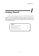
Getting Started Chapter 1. Getting Started Getting Started 1 Thank you for purchasing the MS-6575 v1.X M-ATX mainboard. The MS-6575 v1.X is based on SiS 645/650 & SiS 961 chipsets for optimal system efficiency. Designed to fit the advanced Intel® Pentium® 4 processors in the 478 pin package, the MS-6575 delivers a high performance and professional desktop platform solution.
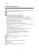
Chapter 1 Mainboard Specification CPU Support Socket 478 for Intel® Pentium 4 Williamette & Northwood processors Core Frequency from 1.7 GHz to 2.2 GHz Chipset SiS 645/650 HMAL/IGUI HMAL (702-pin BGA) - High performance host interface (400MHz) - 64-bit performance DDR333/DDR266/DDR200 memory controller - Integrated A.G.P.
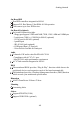
Getting Started On-Board IDE Dual IDE controllers integrated in SiS 961 Support P/O, Bus Master, Ultra DMA 66/100 operation Can connect up to four IDE devices. On-Board Peripherals On-board Peripherals include: - 1 floppy port supports 2 FDD with 360K, 720K, 1.2M, 1.44M and 2.
Chapter 1 Mainboard Layout T: mouse B: keyboard CPUFAN1 ATX Power Supply JPW1 DDR 1 DDR 2 FDD1 PWRFAN1 Top : Game port JP1 SiS 645/650 BIOS Winbond W83697HF IDE 1 CD_IN1 IDE 2 Bottom: Line-Out Line-In Mic IR1 AGP Slot CHSFAN1 RTL 8139C PCI Slot 1 BATT + PCI Slot 2 Codec PCI Slot 3 JABAT1 CNR JFP1 SiS 961 JAUD1 JSMI1 JCI1 MS-6575 v1.
Getting Started Quick Components Guide Component CONN1 JPW1 JKBMS1 JKBMS1 COM A & B (optional) VGA Connector (optional) LPT1 FDD1 IR1 IDE1~ IDE2 CD_IN1 CPUFAN1/CHSFAN1/ PWRFAN1 JWR1/JWL1 JSMI1 JCI1 JFP1 JAUD1 JUSB1 & JUSB4 JBAT1 JP1 AGP Slot PCI Slots CNR Slot Function ATX 20-pin power connector ATX 12V power connector Mouse connector Keyboard connector Serial port connectors Connecting to VGA monitor Parallel port connector Floppy disk drive connector IrDA infrared module connector Hard disk connectors C
Hardware Setup Chapter 2. Hardware Setup Hardware Setup 2 This chapter provides you with the information about hardware setup procedures. While doing the installation, be careful in holding the components and follow the installation procedures. For some components, if you install in the wrong orientation, the components will not work properly. Use a grounded wrist strap before handling computer components. Static electricity may damage the components.
Chapter 2 Central Processing Unit: CPU The mainboard supports Intel® Pentium® 4 processor in the 478 pin package. The mainboard uses a CPU socket called PGA478 for easy CPU installation. When you are installing the CPU, make sure the CPU has a heat sink and a cooling fan attached on the top to prevent overheating. If you do not find the heat sink and cooling fan, contact your dealer to purchase and install them before turning on the computer. CPU Installation Procedures Open Lever 1.
Hardware Setup Installing the CPU Fan As processor technology pushes to faster speeds and higher performance, thermal management becomes increasingly important. To dissipate heat, you need to attach the CPU cooling fan and heatsink on top of the CPU. Follow the instructions below to install the Heatsink/Fan: 1. Locate the CPU and its retention mechanism on the motherboard. 2. Position the heatsink onto the retention mechanism. retention mechanism 3. Mount the fan on top of the heatsink.
Chapter 2 5. Connect the fan power cable from the mounted fan to the 3-pin fan power connector on the board. fan power cable CPU Core Speed Derivation Procedure If CPU Clock Core/Bus ratio then CPU core speed WARNING! = = = = = 100MHz 14 Host Clock x Core/Bus ratio 100MHz x 14 1.4GHz Overclocking This motherboard is designed to support overclocking. However, please make sure your components are able to tolerate such abnormal setting, while doing overclocking.
Hardware Setup Memory The mainboard provides 2 slots for 184-pin, 2.5V unbuffered DDR DIMM with 4 memory banks. You can install PC1600/PC2100 DDR/PC2700 SDRAM modules on the DDR DIMM slots (DDR 1~2). To operate properly, at least one DIMM module must be installed. DDR DIMM Slots Introduction to DDR SDRAM DDR (Double Data Rate) SDRAM is similar to conventional SDRAM, but doubles the rate by transferring data twice per cycle. It uses 2.5 volts as opposed to 3.
Chapter 2 DDR Module Combination You can install either single-sided or double-sided 184-pin DDR DIMM modules into DDR DIMM slots to meet your needs. Different from the SDR DIMM, the DDR DIMM has only one notch on the center of module. The number of pins on either side of the breaks are different. The module will only fit in the right orientation.
Hardware Setup Power Supply The mainboard supports ATX power supply for the power system. Before inserting the power supply connector, always make sure that all components are installed properly to ensure that no damage will be caused. ATX 20-Pin Power Connector: CONN1 This connector allows you to connect to an ATX power supply. To connect to the ATX power supply, make sure the plugs of the power supply is inserted in the proper orientation and the pins are aligned.
Chapter 2 Back Panel The Back Panel provides the following connectors: For SiS 650 Chipset Mouse Keyboard Midi/Joystick Parallel Port COM A VGA Lan Jack L-out L-in MIC USB Ports For SiS 645 Chipset Mouse Keyboard Midi/Joystick Parallel Port COM A COM B 2-8 Lan Jack L-out L-in MIC USB Ports
Hardware Setup Keyboard Connector: JKBMS1 The mainboard provides a standard PS/2® keyboard mini DIN connector for attaching a PS/2® keyboard. You can plug a PS/2® keyboard directly into this connector.
Chapter 2 Joystick/Midi Connectors You can connect a joystick or game pad to this connector. Audio Port Connectors Line Out is a connector for Speakers or Headphones. Line In is used for external CD player, Tape player, or other audio devices. Mic is a connector for microphones.
Hardware Setup Serial Port Connectors: COM A & COM B (for SiS645) The mainboard offers one 9-pin male DIN connectors as serial port COM A for SiS650 chipset, or two serial ports COM A & B for SiS 645 chipset. Both COMA and COM B are 16550A high speed communication ports that send/ receive 16 bytes FIFOs. You can attach a serial mouse or other serial device directly to them.
Chapter 2 Parallel Port Connector: LPT1 The mainboard provides a 25-pin female centronic connector for LPT. A parallel port is a standard printer port that supports Enhanced Parallel Port (EPP) and Extended Capabilities Parallel Port (ECP) mode.
Hardware Setup RJ-45 LAN Jack (Optional) The mainboard provides a RJ-45 connector that allows your computer to be connected to a network environment.
Chapter 2 Connectors The mainboard provides connectors to connect to FDD, IDE HDD, case, modem, LAN, USB Ports, IR module and CPU/System FAN. Floppy Disk Drive Connector: FDD1 The mainboard provides a standard floppy disk drive connector that supports 360K, 720K, 1.2M, 1.44M and 2.88M floppy disk types. FDD1 IrDA Infrared Module Header: IR1 This connector allows you to connect to IrDA Infrared modules. You must configure the setting through the BIOS setup to use the IR function.
Hardware Setup Hard Disk Connectors: IDE1 & IDE2 The mainboard has a 32-bit Enhanced PCI IDE and Ultra DMA 33/66/100 controller that provides PIO mode 0~4, Bus Master, and Ultra DMA/33/66/100 function. You can connect up to four hard disk drives, CD-ROM, 120MB Floppy (reserved for future BIOS) and other devices. These connectors support the provided IDE hard disk cable. IDE2 IDE1 IDE1 (Primary IDE Connector) The first hard drive should always be connected to IDE1.
Chapter 2 CD-In Connector: CD_IN1 The connectors are for CD-ROM audio connectors.
Hardware Setup Fan Power Connectors: CPUFAN1/CHSFAN1/PWRFAN1 The CPUFAN1 (processor fan), CHSFAN1 (system fan) and PWRFAN1 (power fan) support system cooling fan with +12V. It supports three-pin head connector. When connecting the wire to the connectors, always take note that the red wire is the positive and should be connected to the +12V, the black wire is Ground and should be connected to GND.
Chapter 2 Wake On Ring Connector: JWR1 This connector allows you to connect to a modem card with Wake On Ring function. The connector will power up the system when a signal is received through the modem card. JWR1 is compliant with Intel® Front Panel I/ O Connectivity Design Guide. Pin 1 2 3 4 5 Signal NC GND MDM_WAKEUP NC 5VSB 1 5 JWR1 Wake On LAN Connector: JWL1 This connector allows you to connect to a LAN card with Wake On LAN function.
Hardware Setup Power Saving Switch Connector: JSMI1 Attach a power saving switch to this connector. Pressing the switch once will have the system enter the sleep/suspend state. Press any key to wake up the system. 1 JSMI1 Chassis Intrusion Switch Connector: JCI1 This connector is connected to a 2-pin chassis switch. If the chassis is opened, the switch will be short connected. The system will record this status and show a warning message on the screen.
Chapter 2 Front Panel Connector: JFP1 The mainboard provides one front panel connector for establishing electrical connection to the front panel switches and LEDs. JFP1 is compliant with Intel® Front Panel I/O Connectivity Design Guide.
Hardware Setup Front Panel Audio Connector: JAUD1 You can connect an optional audio connector to the JAUD1 front panel audio connector. JAUD1 is compliant to Intel® Front Panel I/O Connectivity Design Guide.
Chapter 2 Front USB Connectors: JUSB1 & JUSB4 The mainboard provides two front Universal Serial Bus connectors for you to connect to USB devices. JUSB1 & JUSB4 are compliant with Intel® Front Panel I/O Connectivity Design Guide.
Hardware Setup Jumpers The motherboard provides one jumper for you to set the computers function. This section will explain how to change your motherboards function through the use of the jumper. Clear CMOS Jumper: JBAT1 There is a CMOS RAM on board that has a power supply from external battery to keep the data of system configuration. With the CMOS RAM, the system can automatically boot OS every time it is turned on. That battery has long life time for at least 5 years.
Chapter 2 BIOS Flash Jumper: JP1 The jumper is used to lock or unlock the boot block area on the BIOS. When unlocked, the BIOS boot block area can be updated. When locked, the area cannot be updated.
Hardware Setup Slots The motherboard provides three 32-bit Master PCI bus slots, one AGP slot and one CNR slot. AGP Slot PCI Slots CNR Slot AGP (Accelerated Graphics Port) Slot The AGP slot allows you to insert the AGP graphics card. AGP is an interface specification designed for the throughput demands of 3D graphics. It introduces a 66MHz, 32-bit channel for the graphics controller to directly access main memory and provides three levels of throughputs: 1x (266Mbps), 2x (533Mbps) and 4x (1.07Gbps).
Chapter 2 CNR (Communication Network Riser) The CNR slot allows you to insert the CNR expansion cards. CNR is a specially designed network, audio, or modem riser card for ATX family motherboards. Its main processing is done through software and controlled by the motherboards chipset. PCI Interrupt Request Routing The IRQ, abbreviation of interrupt request line and pronounced I-R-Q, are hardware lines over which devices can send interrupt signals to the microprocessor.
BIOS Setup 3 Chapter 3. BIOS Setup BIOS Setup This chapter provides information on the BIOS Setup program and allows you to configure the system for optimum use. You may need to run the Setup program when: An error message appears on the screen during the system booting up, and requests you to run SETUP. You want to change the default settings for customized features.
Chapter 3 Entering Setup Power on the computer and the system will start POST (Power On Self Test) process. When the message below appears on the screen, press key to enter Setup. Press DEL to enter SETUP If the message disappears before you respond and you still wish to enter Setup, restart the system by turning it OFF and On or pressing the RESET button. You may also restart the system by simultaneously pressing , , and keys.
BIOS Setup Getting Help After entering the Setup menu, the first menu you will see is the Main Menu. Main Menu The main menu lists the setup functions you can make changes to. You can use the control keys ( ↑↓ ) to select the item. The on-line description of the highlighted setup function is displayed at the bottom of the screen.
Chapter 3 The Main Menu Once you enter Award® BIOS CMOS Setup Utility, the Main Menu (Figure 1) will appear on the screen. The Main Menu allows you to select from twelve setup functions and two exit choices. Use arrow keys to select among the items and press to accept or enter the sub-menu. Standard CMOS Features Use this Menu for basic system configurations. Advanced BIOS Features Use this menu to set the Advanced Features available on your system.
BIOS Setup PC Health Status This entry shows your PC health status. Frequency/Voltage Control Use this menu to specify your settings for frequency/voltage control. Load Fail-Safe Defaults Use this menu to load the BIOS default values for minimal but stable system performance. Load Optimized Defaults Use this menu to load the BIOS default values that are factory settings for optimal system operations. Set Supervisor/User Password Use this menu to set User and Supervisor Passwords.
Chapter 3 Standard CMOS Features The items in Standard CMOS Features Menu are divided into 10 categories. Each category includes no, one or more than one setup items. Use the arrow keys to highlight the item and then use the or keys to select the value you want in each item. Date The date format is . day Day of the week, from Sun to Sat, determined by BIOS. Read-only. month The month from Jan. through Dec.
BIOS Setup ing items. Enter the information directly from the keyboard. This information should be provided in the documentation from your hard disk vendor or the system manufacturer. If the controller of HDD interface is SCSI, the selection shall be None. If the controller of HDD interface is CD-ROM, the selection shall be None. Access Mode The settings are CHS, LBA, Large, Auto. Capacity The formatted size of the storage device. Cylinder Number of cylinders. Head Number of heads.
Chapter 3 Advanced BIOS Features Anti-Virus Protection The item is to set the Virus Warning feature for IDE Hard Disk boot sector protection. If the function is enabled and any attempt to write data into this area is made, BIOS will display a warning message on screen and beep. Settings: Disabled and Enabled. CPU L1 & L2 Cache The item allows you to turn on or off CPUs internal (L1) and external (L2) cache. Settings: Enabled and Disabled.
BIOS Setup First/Second/Third Boot Device The items allow you to set the sequence of boot devices where BIOS attempts to load the disk operating system. The settings are: Floppy The system will boot from floppy drive. LS120 The system will boot from LS-120 drive. HDD-0 The system will boot from the first HDD. SCSI The system will boot from the SCSI. CDROM The system will boot from the CD-ROM. HDD-1 The system will boot from the second HDD. HDD-2 The system will boot from the third HDD.
Chapter 3 Typematic Rate Setting This item is used to enable or disable the typematic rate setting including Typematic Rate & Typematic Delay. Typematic Rate (Chars/Sec) After Typematic Rate Setting is enabled, this item allows you to set the rate (characters/second) at which the keys are accelerated. Settings: 6, 8, 10, 12, 15, 20, 24 and 30. Typematic Delay (Msec) This item allows you to select the delay between when the key was first pressed and when the acceleration begins.
BIOS Setup HDD S.M.A.R.T. Capability This allows you to activate the S.M.A.R.T. (Self-Monitoring Analysis & Reporting Technology) capability for the hard disks. S.M.A.R.T is a utility that monitors your disk status to predict hard disk failure. This gives you an opportunity to move data from a hard disk that is going to fail to a safe place before the hard disk becomes offline. Settings: Enabled and Disabled.
Chapter 3 Advanced Chipset Features The Advanced Chipset Features Setup option is used to change the values of the chipset registers. These registers control most of the system options in the computer. Note: Change these settings only if you are familiar with the chipset. Advanced DRAM Control 1 Press to enter the sub-menu and the following screen appears: System Performance The DRAM timing is controlled by the DRAM Timing Registers.
BIOS Setup Timings programmed into this register are dependent on the system design. Slower rates may be required in certain system designs to support loose layouts or slower memory. Setting options: Safe Mode, Normal Mode, Fast Mode, Turbo Mode, Ultra Mode. CAS Latency Setting When synchronous DRAM is installed, the number of clock cycles of CAS latency depends on the DRAM timing. The settings are: 2T, 2.5T, 3T. Memory Hole At 15M-16M You can reserve this area of system memory for ISA adapter ROM.
Chapter 3 Integrated Peripherals SiS OnChip IDE Device Press to enter the sub-menu and the following screen appears: Internal PCI/IDE This setting enables or disables the internal primary and secondary PCI & IDE controllers. Setting options: Disabled, Primary, Secondary, Both.
BIOS Setup mode (0-4) for each of the four IDE devices that the onboard IDE interface supports. Modes 0 through 4 provide successively increased performance. In Auto mode, the system automatically determines the best mode for each device. The settings are: Auto, Mode 0, Mode 1, Mode 2, Mode 3, Mode 4.
Chapter 3 SiS-7013 S/W Modem This setting enables or disables the SiS-7013 S/W modem. Setting options: Disabled, Enabled. System Share Memory Size (for SiS650 chipset only) For SiS650 chipset, the system shares memory to the onboard VGA card. This setting controls the exact memory size shared to the VGA card. Setting options: 4MB, 8MB, 16MB, 32MB, 64MB. TV System This option will show up only if a TV is connected to your system. This feature allows you to specify your TV system.
BIOS Setup UART Mode Select This setting allows you to specify the operation mode for serial port 2. Setting options: IrDA, ASKIR, Normal. Normal RS-232C Serial Port IrDA IrDA-compliant Serial Infrared Port ASKIR Amplitude Shift Keyed Infrared Port RxD, TxD Active This setting controls the receiving and transmitting speed of the IR peripheral in use. Setting options: Hi/Hi, Hi/Lo, Lo/Hi, Lo/Lo.
Chapter 3 ECP + EPP: Extended Capability Port + Enhanced Parallel Port SPP/EPP/ECP/ECP+EPP To operate the onboard parallel port as Standard Parallel Port only, choose SPP. To operate the onboard parallel port in the EPP mode simultaneously, choose EPP. By choosing ECP, the onboard parallel port will operate in ECP mode only. Choosing ECP + EPP will allow the onboard parallel port to support both the ECP and EPP modes simultaneously. EPP Mode Select The onboard parallel port is EPP Spec.
BIOS Setup Onboard LAN function (Optional) Select Enabled to activate the onboard LAN controller. Setting options: Enabled, Disabled. Onboard Lan Boot ROM (Optional) This setting determines whether or not to activate the boot ROM of the onboard LAN chip. Setting options: Enabled, Disabled. IDE HDD Block Mode Block mode is also called block transfer, multiple commands, or multiple sector read/write.
Chapter 3 Power Management Setup The Power Management Setup allows you to configure you system to most effectively save energy while operating in a manner consistent with your own style of computer use. IPCA Function This item is to activate the ACPI (Advanced Configuration and Power Management Interface) Function. If your operating system is ACPI-aware, such as Windows® 98SE/2000/ME, select Enabled. Settings: Enabled and Disabled.
BIOS Setup Video Off Option This setting is used to control the mode in which the monitor will shut down. Setting options: Always On Always turn on. Suspend -> Off During suspend mode, the monitor will shut down. Susp, Stby->Off During suspend or standby mode, the monitor will shut down. All Modes ->Off The monitor is turned off during doze, standby, or suspend mode. Video Off Method This determines the manner in which the monitor is blanked.
Chapter 3 the sleep state. Available options are: Single LED The power LED turns off to indicate the sleep state. Dual LED The power LED changes its color to indicate the sleep state. After AC Power Lost This item specifies whether your system will reboot after a power failure or interrupt occurs. Available settings are: Power Off Leaves the computer in the power off state. Power On Reboots the computer. Last State Restores the system to the status before power failure or interrupt occurred.
BIOS Setup RING Power Up Control, PCI PME Power Up Control, USB Port Wake Up Control, PS2MS Wakeup from S3 These fields specify whether the system will be awakened from power saving modes when activity or input signal of the specified hardware peripheral or component is detected. Settings are: Enabled and Disabled. Note: To use the function of RING Power Up Control, you need to install a modem supporting power on function. PS2KB Wakeup From S3 This setting allows you to enter Any Key (max.
Chapter 3 PnP/PCI Configurations This section describes configuring the PCI bus system. PCI, or Peripheral Component Interconnect, is a system which allows I/O devices to operate at speeds nearing the speed the CPU itself uses when communicating with its own special components. This section covers some very technical items and it is strongly recommended that only experienced users should make any changes to the default settings. Reset Configuration Data Normally, you leave this field Disabled.
BIOS Setup Press and you will enter the sub-menu of the items. IRQ Resources list IRQ 3/4/5/7/9/10/11/12/14/15 for users to set each IRQ a type depending on the type of device using the IRQ. Settings are: PCI Device For Plug & Play compatible devices designed for PCI bus architecture. Reserved The IRQ will be reserved for further request.
Chapter 3 PC Health Status This section shows the status of your CPU, fan, warning for overall system status. Monitor function is available only if there is hardware monitoring mechanism onboard. CPU Warning Temperature If the CPU temperature reaches the upper limit preset in this setting, the warning mechanism will be activated. This helps you to prevent the CPU overheat problem. Current System/CPU Temperature, CPU/System fan, Vcore, 3.
BIOS Setup Frequency/Voltage Control This section describes how to set the CPU FSB frequency, spread spectrum, clock ratio etc. CPU Clock Ratio End users can overclock the processor by specifying the CPU ratio (clock multiplier) in this field. Auto Detect DIMM/PCI Clk This option allows you to enable/disable the feature of auto detecting the clock frequency of the installed DIMM/PCI bus. The settings are: Enabled, Disabled.
Chapter 3 DRAM Frequency Use this item to select the appropriate frequency for your DDR SDRAM modules. Options are: 200MHz, 266MHz, 333MHz and By SPD.
BIOS Setup Load Fail-Safe/Optimized Defaults The two options on the main menu allow users to restore all of the BIOS settings to the default Fail-Safe or Optimized values. The Optimized Defaults are the default values set by the mainboard manufacturer specifically for optimal performance of the mainboard. The Fail-Safe Defaults are the default values set by the BIOS vendor for stable system performance.
Chapter 3 Set Supervisor/User Password When you select this function, a message as below will appear on the screen: Type the password, up to eight characters in length, and press . The password typed now will replace any previously set password from CMOS memory. You will be prompted to confirm the password. Retype the password and press . You may also press to abort the selection and not enter a password.