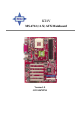
KT4V MS-6712 (v1.X) ATX Mainboard Version 1.
Manual Rev: 1.0 Release Date: Aug. 2002 FCC-B Radio Frequency Interference Statement This equipment has been tested and found to comply with the limits for a class B digital device, pursuant to part 15 of the FCC rules. These limits are designed to provide reasonable protection against harmful interference when the equipment is operated in a commercial environment.
Copyright Notice The material in this document is the intellectual property of MICRO-STAR INTERNATIONAL. We take every care in the preparation of this document, but no guarantee is given as to the correctness of its contents. Our products are under continual improvement and we reserve the right to make changes without notice. Trademarks All trademarks are the properties of their respective owners. AMD, Athlon™, Athlon™ XP, Thoroughbred™, and Duron™ are registered trademarks of AMD Corporation.
Safety Instructions 1. 2. 3. 4. 5. Always read the safety instructions carefully. Keep this User’s Manual for future reference. Keep this equipment away from humidity. Lay this equipment on a reliable flat surface before setting it up. The openings on the enclosure are for air convection hence protects the equipment from overheating. DO NOT COVER THE OPENINGS. 6. Make sure the voltage of the power source and adjust properly 110/220V before connecting the equipment to the power inlet. 7.
CONTENTS FCC-B Radio Frequency Interference Statement .......................................... iii Copyright Notice .......................................................................................... iii Revision History ........................................................................................... iii Technical Support ......................................................................................... iii Safety Instructions ......................................................
Installing DDR Modules ............................................................... 2-8 Power Supply ....................................................................................... 2-9 ATX 20-Pin Power Connector: JWR1 ............................................ 2-9 Back Panel .......................................................................................... 2-10 Mouse Connector ....................................................................... 2-10 Keyboard Connector ...............
PCI Interrupt Request Routing .................................................... 2-29 Chapter 3. BIOS Setup .............................................................................. 3-1 Entering Setup ...................................................................................... 3-2 Selecting the First Boot Device ..................................................... 3-2 Control Keys ................................................................................. 3-3 Getting Help ...........
Getting Started Chapter 1. Getting Started Getting Started Thank you for purchasing the MS-6712 v1.X ATX mainboard. The MS-6712 v1.X ATX mainboard is based on VIA® Apollo KT400 North Bridge & VT8235 South Bridge) chipset for optimal system efficiency. Designed to fit the advanced AMD® Athlon™, Athlon™ XP or Duron™ processors, the MS-6712 delivers a high performance and professional desktop platform solution.
MS-6712 ATX Mainboard Mainboard Specifications CPU h Supports Socket A (Socket-462) for AMD® Athlon™/Athlon™ XP /Duron™ processors h Supports up to 2200+ (1.
Getting Started - Vertical audio ports - 1 SPDIF output (1 x 3) with housing (Optional) - 6 USB ports (Rear * 4/ Front * 2) Bluetooth (Optional) h 1 Bluetooth connector for wireless connection Audio h RealTek ALC650 6-channel audio LAN h VIA VT6103 LAN controller BIOS h The mainboard BIOS provides “Plug & Play” BIOS which detects the peripheral devices and expansion cards of the board automatically.
MS-6712 ATX Mainboard Mainboard Layout Top : mouse Bottom: keyboard CFAN1 SOCKET 462 ATX Power Supply USB ports Top : Parallel Port Bottom: COM A COM B FDD 1 VIA KT400 T: LAN jack B: USB ports VIA VT6103 DDR 3 DDR 1 AGP Slot JCD1 DDR 2 Line-Out Line-In Mic PCI Slot 1 Winbond W83697HF BI OS PCI Slot 2 JCI1 PCI Slot 3 VIA VT8235 JIR1 JSP3 PCI Slot 4 SFAN1 Codec JBAT1 IDE 1 PCI Slot 5 IDE 2 JLED1 BATT + CNR PCI Slot 6 JAUD1 JUSB1 JBT1 MS-6712 v1.
Getting Started MSI Special Features PC Alert™ 4 The PC AlertTM 4 is a utility you can find in the CD-ROM disk. The utility is just like your PC doctor that can detect the following PC hardware status during real time operation: Ø monitor CPU & system temperatures Ø monitor fan speed(s) Ø monitor system voltage If one of the items above is abnormal, the program main screen will be immediately shown on the screen, with the abnormal item highlighted in red.
MS-6712 ATX Mainboard Live BIOS™/Live Driver™ The Live BIOS™/Live Driver™ is a tool used to detect and update your BIOS/drivers online so that you don’t need to search for the correct BIOS/driver version throughout the whole Web site. To use the function, you need to install the “MSI Live Update Series 2” application. After the installation, the “MSI Live Update Series 2” icon (as shown on the right) will appear on the screen.
Getting Started Live Monitor™ The Live Monitor™ is a tool used to schedule the search for the latest BIOS/drivers version on the MSI Web site. To use the function, you need to install the “MSI Live Update Series 2” application. After the installation, the “MSI Live Monitor” icon (as shown on the right) will appear on the screen. Double click this icon to run the application. Double click the “MSI Live Monitor” icon at the lower-right corner of the taskbar, and the following dialog box will appear.
MS-6712 ATX Mainboard D-Bracket™ 2 (Optional) D-Bracket™ 2 is a USB bracket integrating four Diagnostic LEDs, which use graphic signal display to help users understand their system. The LEDs provide up to 16 combinations of signals to debug the system. The 4 LEDs can detect all problems that fail the system, such as VGA, RAM or other failures. This special feature is very useful for overclocking users. These users can use the feature to detect if there are any problems or failures.
Getting Started Red Green D-Bracket™ 2 Description Processor Initialization - This will show information regarding the processor (like brand name, system bus, etc…) Testing RTC (Real Time Clock) Initializing Video Interface - This will start detecting CPU clock, checking type of video onboard. Then, detect and initialize the video adapter. BIOS Sign On - This will start showing information about logo, processor brand name, etc….
MS-6712 ATX Mainboard Fuzzy Logic™ 4 The Fuzzy Logic™ 4 utility is a user friendly tool that allows users to view and adjust the current system status. To overclock the CPU FSB (Front Side Bus) frequency under the Windows operating system, click FSB and use the right and left arrow keys to select the desired FSB, and then click Apply to apply the new setup value. To enable the system running at the specified FSB every time when you click Turbo, click Save to save the desired FSB first.
Getting Started CPU Thermal Protection Aimed to prevent the CPU from overheating, MSI has developed a CPU Thermal Protection mechanism for AMD Athlon™ XP CPU platform. This CPU Thermal Protection mechanism works on a thermal signal sensor. If the mechanism senses an abnormal temperature rise, it will automatically shut down the system and the CPU temperature will then drop down and resume normal. With this unique feature, users can better protect their CPU.
MS-6712 ATX Mainboard MSI DVD 5.1 Channel (Optional) The motherboard comes with MSI DVD application which supports 5.1 channel (6-channel audio) operation. The accompanying MSI DVD is a convenient tool to meet increasing demands for home entertainment. To play DVD with 6-channel audio output, you must configure both the MSI DVD application and the audio codec’s software utility. Otherwise, the 6channel audio function will not work properly.
Getting Started 4. Click OK. For more information about MSI DVD, you can refer to the online help coming with the application. To enter the online help: 1. Click on the icon at the bottom-right corner of the control panel. 2. The following window appears. Click here 3. Click MSIDVD FAQ.
Hardware Setup Chapter 2. Hardware Setup Hardware Setup This chapter tells you how to install the CPU, memory modules, and expansion cards, as well as how to setup the jumpers on the mainboard. Also, it provides the instructions on connecting the peripheral devices, such the mouse, keyboard, etc. While doing the installation, be careful in holding the components and follow the installation procedures.
MS-6712 ATX Mainboard Quick Components Guide JWR1, p.2-9 CPU, p.2-3 CFAN1, p.2-17 DDR DIMMs, p.2-7 Back Panel I/O, p.2-10 FDD1, p.2-15 JCD1, p.2-26 AGP Slot, p.2-28 PCI Slots, p.2-28 JCI1, p.2-25 JSP3, p.2-23 JIR1, p.2-25 SFAN1, p.2-17 JBAT1, p.2-27 IDE1 IDE2, p.2-16 JFP1 & JFP2, p.2-18 JAUD1, p.2-19 CNR Slot, p.2-28 2-2 JLED1, p.2-22 JBT1, p.2-21 JUSB1, p.
Hardware Setup Central Processing Unit: CPU The mainboard supports AMD® Athlon™, Athlon™ XP and Duron™ processors in the 462 pin package. The mainboard uses a CPU socket called Socket A for easy CPU installation. When you are installing the CPU, make sure the CPU has a heat sink and a cooling fan attached on the top to prevent overheating. If you do not find the heat sink and cooling fan, contact your dealer to purchase and install them before turning on the computer.
MS-6712 ATX Mainboard CPU Installation Procedures for Socket 462 1. Please turn off the power and unplug the power cord before installing the CPU. 2. Pull the lever sideways away from the socket. Make sure to raise the lever up to a 90degree angle. 3. Look for the gold arrow. The gold arrow should point towards the lever pivot. The CPU can only fit in the correct orientation. 4. If the CPU is correctly installed, the pins should be completely embedded into the socket and can not be seen.
Hardware Setup Installing AMD Athlon CPU (Socket 462) Cooler Set The following instructions will guide you through the heat sink installation procedures. Please consult your agent for the proper CPU cooler set. 1. Position your CPU cooler set onto the CPU. Apply some heat sink paste 2. Use one end of the clip to hook the latch of the CPU sliding plate. 3. Hook the other latch to fix the cooling fan set. You may need a screw drive to press down the other side of the clip. 4.
MS-6712 ATX Mainboard CPU Clock Frequency Selection through BIOS The hardware configuration for CPU clock frequency of the motherboard is set to 100MHz by default. Therefore, to make a 133MHz CPU run at 133MHz when it is installed on the board, you have to adjust the CPU clock frequency in the BIOS setup utility. To set the clock frequency for the installed CPU, refer to Frequency/ Voltage Control in Chapter 3. BIOS Setup. MSI Reminds You...
Hardware Setup Memory The mainboard provides 3 slots for 184-pin DDR SDRAM DIMM (Double In-Line Memory Module) modules and supports the memory size up to 3GB. You can install PC2700/DDR333, PC2100/DDR266 or PC1600/ DDR200 modules on the DDR DIMM slots (DIMM 1~3). DDR DIMM Slots (DDR 1~3) Introduction to DDR SDRAM DDR (Double Data Rate) SDRAM is similar to conventional SDRAM, but doubles the rate by transferring data twice per cycle. It uses 2.5 volts as opposed to 3.
MS-6712 ATX Mainboard DIMM Module Combination Install at least one DIMM module on the slots. You can install either single- or double-sided modules in any order to meet your own needs. Memory modules can be installed in any combination as follows: Slot Memory Module Total Memory DIMM 1 (Bank 0 & 1) S/D 64MB~1GB DIMM 2 (Bank 2 & 3) S/D 64MB~1GB DIMM 3 (Bank 4 & 5) S/D 64MB~1GB Maximum System Memory Suppported 64MB~3GB S: Single Side D: Double Side Installing DDR Modules 1.
Hardware Setup Power Supply The mainboard supports ATX power supply for the power system. Before inserting the power supply connector, always make sure that all components are installed properly to ensure that no damage will be caused. ATX 20-Pin Power Connector: JWR1 This connector allows you to connect to an ATX power supply. To connect to the ATX power supply, make sure the plug of the power supply is inserted in the proper orientation and the pins are aligned.
MS-6712 ATX Mainboard Back Panel The back panel provides the following connectors: LAN (Optional) Parallel Mouse MIC L-in L-out Keyboard USB COM A COM B USB Mouse Connector The mainboard provides a standard PS/2® mouse mini DIN connector for attaching a PS/2® mouse. You can plug a PS/2® mouse directly into this connector.
Hardware Setup Keyboard Connector The mainboard provides a standard PS/2® keyboard mini DIN connector for attaching a PS/2® keyboard. You can plug a PS/2® keyboard directly into this connector.
MS-6712 ATX Mainboard Parallel Port Connector: LPT1 The mainboard provides a 25-pin female centronic connector as LPT. A parallel port is a standard printer port that supports Enhanced Parallel Port (EPP) and Extended Capabilities Parallel Port (ECP) mode.
Hardware Setup Audio Port Connectors Line Out is a connector for Speakers or Headphones. Line In is used for external CD player, Tape player, or other audio devices. Mic is a connector for microphones. 1/8” Stereo Audio Connectors MIC Line In Line Out MSI Reminds You... For advanced audio application, RealTek ALC650 audio chip is provided as an option to offer support for 6-channel audio operation and can turn rear audio connectors from 2-channel to 4-/6-channel audio.
MS-6712 ATX Mainboard Serial Port Connectors: COM A & COM B The mainboard offers two 9-pin male DIN connectors as serial port COM A & COM B. The ports are 16550A high speed communication ports that send/receive 16 bytes FIFOs. You can attach a serial mouse or other serial devices directly to the connectors.
Hardware Setup Connectors The mainboard provides connectors to connect to FDD, IDE HDD, case, modem, LAN, USB Ports, IR module and CPU/System FAN. Floppy Disk Drive Connector: FDD1 The mainboard provides a standard floppy disk drive connector that supports 360K, 720K, 1.2M, 1.44M and 2.88M floppy disk types.
MS-6712 ATX Mainboard Hard Disk Connectors: IDE1 & IDE2 The mainboard has a 32-bit Enhanced PCI IDE and Ultra DMA 33/66/ 100/133 controller that provides PIO mode 0~4, Bus Master, and Ultra DMA 33/66/100/133 function. You can connect up to four hard disk drives, CDROM, 120MB Floppy (reserved for future BIOS) and other devices. IDE 1 IDE 2 IDE1 (Primary IDE Connector) The first hard drive should always be connected to IDE1. IDE1 can connect a Master and a Slave drive.
Hardware Setup Fan Power Connectors: CFAN1/SFAN1 The CFAN1 (processor fan) and SFAN1 (system fan) support system cooling fan with +12V. It supports three-pin head connector. When connecting the wire to the connectors, always take note that the red wire is the positive and should be connected to the +12V, the black wire is Ground and should be connected to GND.
MS-6712 ATX Mainboard Front Panel Connectors: JFP1 & JFP2 The mainboard provides two front panel connectors for electrical connection to the front panel switches and LEDs. JFP1 is compliant with Intel® Front Panel I/O Connectivity Design Guide.
Hardware Setup Front Panel Audio Connector: JAUD1 The JAUD1 front panel audio connector allows you to connect to the front panel audio and is compliant with Intel® Front Panel I/O Connectivity Design Guide.
MS-6712 ATX Mainboard Front USB Connector: JUSB1 The mainboard provides one USB 2.0 pinheader. The JUSB1 is compliant with Intel® I/O Connectivity Design Guide. JUSB1 Pin Definition Pin Description Pin Description 1 VCC 2 VCC 3 USB0- 4 USB1- 5 USB0+ 6 USB1+ 7 GND 8 GND 9 Key 10 USBOC 2 1 10 9 JUSB1 (USB 1.1/Intel spec) MSI Reminds You... The USB 2.0 technology is downward compatible with USB 1.1 spec. To use the USB 2.0 ports, you have to install the USB 2.
Hardware Setup Bluetooth Connector: JBT1 (Optional) This connector is used to connect a bluetooth module for wireless connection. 7 1 8 2 JBT1 Pin Definition PIN SIGNAL PIN SIGNAL 1 5VDUAL 2 3VDUAL 3 5 7 D+ (USB signal) D- (USB signal) GND 4 6 8 GND GND NC MSI Reminds You... Because the bluetooth connector shares the USB interface with the onboard USB pinheader, the bottommost USB port will not function when you attach a bluetooth module to this connector.
MS-6712 ATX Mainboard D-Bracket™ 2 Connector: JLED1 The mainboard comes with a JLED1 connector for you to connect to DBracket™ 2. D-Bracket™ 2 is a USB Bracket that supports both USB1.1 & 2. 0 spec. It integrates four LEDs and allows users to identify system problem through 16 various combinations of LED signals. For definitions of 16 signal combinations, please refer to D-Bracket™ 2 (Optional) in Chapter 1.
Hardware Setup S-Bracket Connector: JSP3 The connector allows you to connect a S-Bracket for Sony & Philips Digital Interface (SPDIF). The S-Bracket offers 2 SPDIF jacks for digital audio transmission (one for optical fiber connection and the other for coaxial), and 2 analog Line-Out jacks for 4-channel audio output. To attach the fiber-optic cable to optical SPDIF jack, you need to remove the plug from the jack first. The two SPDIF jacks support SPDIF output only.
MS-6712 ATX Mainboard Optional S-Bracket CEN/SUB RL/RR Connect to JSP3 SPDIFJack (optical) 2-24 SPDIF Jack (coaxial) Analog Line-Out Jacks
Hardware Setup IrDA Infrared Module Header: JIR1 The connector allows you to connect to IrDA Infrared module. You must configure the setting through the BIOS setup to use the IR function. JIR1 is compliant with Intel® Front Panel I/O Connectivity Design Guide. JIR1 Pin Definition 6 5 2 1 JIR1 Pin Signal 1 2 3 4 5 6 NC NC VCC5 GND IRTX IRRX Chassis Intrusion Switch Connector: JCI1 This connector is connected to a 2-pin chassis switch. If the chassis is opened, the switch will be short.
MS-6712 ATX Mainboard CD-In Connector: JCD1 The connector is for CD-ROM audio connector.
Hardware Setup Jumpers The motherboard provides the following jumpers for you to set the computer’s function. This section will explain how to change your motherboard’s function through the use of jumpers. Clear CMOS Jumper: JBAT1 There is a CMOS RAM on board that has a power supply from external battery to keep the data of system configuration. With the CMOS RAM, the system can automatically boot OS every time it is turned on.
MS-6712 ATX Mainboard Slots The motherboard provides one AGP slot, six 32-bit PCI bus slots, and one CNR slot. AGP Slot PCI Slots CNR Slot AGP (Accelerated Graphics Port) Slot The AGP slot allows you to insert the AGP graphics card. AGP is an interface specification designed for the throughput demands of 3D graphics. It introduces a 66MHz, 32-bit channel for the graphics controller to directly access main memory. The mainboard supports 4x/8x 1.5V AGP card.
Hardware Setup PCI Interrupt Request Routing The IRQ, acronym of interrupt request line and pronounced I-R-Q, are hardware lines over which devices can send interrupt signals to the microprocessor. For efficient IRQ allocation, PCI slot 1 and slot 6 are designed to share the same IRQs. To install a PCI expansion card on a PCI shared slot, you must make sure the card’s driver supports “IRQ shared” function or there is no need to assign an IRQ to the device.
BIOS Setup Chapter 3. BIOS Setup BIOS Setup This chapter provides information on the BIOS Setup program and allows you to configure the system for optimum use. You may need to run the Setup program when: An error message appears on the screen during the system booting up, and requests you to run SETUP. You want to change the default settings for customized features.
KT3MS-6712 Ultra2-C ATX Mainboard ATX Mainboard Entering Setup Power on the computer and the system will start POST (Power On Self Test) process. When the message below appears on the screen, press key to enter Setup. DEL:Setup F11:Boot Menu F12:Network boot TAB:Logo If the message disappears before you respond and you still wish to enter Setup, restart the system by turning it OFF and On or pressing the RESET button.
BIOS Setup Control Keys < > Move to the previous item < > Move to the next item < > Move to the item on the left-hand side < > Move to the item on the right-hand side <+/PU> Select the item Jumps to the Exit menu or returns to the main menu from a submenu Increase the numeric value or make changes <-/PD> Decrease the numeric value or make changes General help, only for Status Page Setup Menu and Option Page Setup Menu Load the default CMOS value from Fail-Safe default
KT3MS-6712 Ultra2-C ATX Mainboard ATX Mainboard The Main Menu Once you enter AMIBIOS NEW SETUP UTILITY, the Main Menu will appear on the screen. The Main Menu displays twelve configurable functions and two exit choices. Use arrow keys to move among the items and press to enter the sub-menu. Standard CMOS Features Use this menu for basic system configurations, such as time, date etc. Advanced BIOS Features Use this menu to setup the items of AMI® special enhanced features.
BIOS Setup Integrated Peripherals Use this menu to specify your settings for integrated peripherals. PC Health Status This entry shows your PC health status. Frequency/Voltage Control Use this menu to specify your settings for frequency/voltage control. Set Supervisor Password Use this menu to set Supervisor Password. Set User Password Use this menu to set User Password.
KT3MS-6712 Ultra2-C ATX Mainboard ATX Mainboard Standard CMOS Features The items inside STANDARD CMOS FEATURES menu are divided into 9 categories. Each category includes none, one or more setup items. Use the arrow keys to highlight the item you want to modify and use the or keys to switch to the value you prefer. System Time This allows you to set the system time that you want (usually the current time). The time format is .
BIOS Setup cation of hard disk drive will show up on the right hand according to your selection.
KT3MS-6712 Ultra2-C ATX Mainboard ATX Mainboard Advanced BIOS Features Quick Boot Setting the item to Enabled allows the system to boot within 5 seconds since it will skip some check items. Available options: Enabled, Disabled. Full Screen Logo Show This item enables you to show the company logo on the bootup screen. Settings are: Enabled Shows a still image (logo) on the full screen at boot. Disabled Shows the POST messages at boot. Boot Sequency Press to enter the sub-menu screen.
BIOS Setup IDE-2 IDE-3 Floppy ARMD-FDD The system will boot from the third HDD. The system will boot from the fourth HDD. The system will boot from floppy drive. The system will boot from any ARMD device, such as LS-120 or ZIP drive, that functions as a floppy drive. ARMD-HDD The system will boot from ARMD device, such as MO or ZIP drive, that functions as hard disk drive. CD/DVD The system will boot from the CD/DVD ROM. Legacy SCSI The system will boot from the SCSI.
KT3MS-6712 Ultra2-C ATX Mainboard ATX Mainboard USB RMDHDD Disabled The system will boot from USB-interfaced ARMD device, such as MO or ZIP drive, that functions as hard disk drive. Disable this sequence. MSI Reminds You... 1. Available settings for “1st/2nd/3rd Boot Device” vary depending on the bootable devices you have installed. For example, if you did not install a floppy drive, the setting “Floppy” does not show up. 2.
BIOS Setup Primary Display This configures the primary subsystem in the computer. Available options: Mono (monochrome), CGA40x25, CGA80x25, VGA/EGA, Absent. Password Check This specifies the type of AMIBIOS password protection that is implemented. Setting options are described below. Option Setup Always Description The password prompt appears only when end users try to run Setup. A password prompt appears every time when the computer is powered on or when end users try to run Setup.
KT3MS-6712 Ultra2-C ATX Mainboard ATX Mainboard Option Description Disabled Enabled The specified ROM is not copied to RAM. The contents of specified ROM are copied to RAM for faster system performance. The contents of specified ROM are not only copied to RAM, the contents of the ROM area can be written to and read from cache memory. Cached APIC Function This field is used to enable or disable the APIC (Advanced Programmable Interrupt Controller).
BIOS Setup Advanced Chipset Features MSI Reminds You... Change these settings only if you are familiar with the chipset. DRAM Timing Control Press and the following sub-menu appears. Current Host Clock This item shows the current CPU frequency. Configure SDRAM Timing by Selects whether DRAM timing is controlled by the SPD (Serial Presence Detect) EEPROM on the DRAM module.
KT3MS-6712 Ultra2-C ATX Mainboard ATX Mainboard SDRAM Frequency, SDRAM CAS# Latency, Row Precharge Time, RAS Pulse Width, RAS to CAS Delay and SDRAM Bank Interleave automatically to be determined by BIOS based on the configurations on the SPD. Selecting User allows users to configure these fields manually. SDRAM Frequency Use this item to configure the clock frequency of the installed SDRAM. Settings options: 200MHz, 266MHz, 333MHz, 400MHz, Auto.
BIOS Setup DDR DQS Input Delay This setting allows you to set the delay time of DQS to improve the setup time and hold time of the data, and improve the stability. Setting options: Auto, 18, 08, 0E, 0F. SDRAM Burst Length This setting allows you to set the size of Burst-Length for DRAM. Bursting feature is a technique that DRAM itself predicts the address of the next memory location to be accessed after the first address is accessed.
KT3MS-6712 Ultra2-C ATX Mainboard ATX Mainboard AGP Mode The item sets an appropriate mode for the installed AGP card. Setting options: 1x, 2x, 4x, Auto. Select 4x only if your AGP card supports it. AGP Fast Write This option enables or disables the AGP Fast Write feature. The Fast Write technology allows the CPU to write directly to the graphics card without passing anything through the system memory and improves the AGP 4X speed. Select Enabled only when the installed AGP card supports this function.
BIOS Setup Power Management Features MSI Reminds You... S3-related functions described in this section are available only when your BIOS supports S3 sleep mode. IPCA Function This item is to activate the ACPI (Advanced Configuration and Power Management Interface) function. If your operating system is ACPI-aware, such as Windows 98SE/2000/ME, select Yes. Available options: Yes, No. ACPI Standby State This item secifies the power saving modes for ACPI function.
KT3MS-6712 Ultra2-C ATX Mainboard ATX Mainboard Call VGA BIOS at S3 Resuming Selecting Enabled allows BIOS to call VGA BIOS to initialize the VGA card when system wakes up (resumes) from S3 sleep state. The system resume time is shortened when you disable the function, but system will need an AGP driver to initialize the VGA card. Therefore, if the AGP driver of the card does not support the initialization feature, the display may work abnormally or not function after resuming from S3.
BIOS Setup Power Button Function This feature sets the function of the power button. Settings are: On/Off The power button functions as normal power off button. Suspend When you press the power button, the computer enters the suspend/sleep mode, but if the button is pressed for more than four seconds, the computer is turned off. After AC Power Loss This setting specifies whether your system will reboot after a power failure or interrupt occurs.
KT3MS-6712 Ultra2-C ATX Mainboard ATX Mainboard S3 (Suspend to RAM) sleep state. Settings: Disabled, Any Key, Specific Key. Wake-Up Key This setting allows users to set a wake-up key to recall the system from power saving state. Options: Any Key, Specific Key. Wake-Up Password This setting allows users to set a password (max. 5 letters) to wake up the system. Resume On PS/2 Mouse This item allows the activity of the mouse to wake up the system from S3 (Suspend to RAM) sleep state.
BIOS Setup PNP/PCI Configurations This section describes configuring the PCI bus system and PnP (Plug & Play) feature. PCI, or Peripheral Component Interconnect, is a system which allows I/O devices to operate at speeds nearing the speed the CPU itself uses when communicating with its special components. This section covers some very technical items and it is strongly recommended that only experienced users should make any changes to the default settings.
KT3MS-6712 Ultra2-C ATX Mainboard ATX Mainboard PCI Latency Timer This item controls how long each PCI device can hold the bus before another takes over. When set to higher values, every PCI device can conduct transactions for a longer time and thus improve the effective PCI bandwidth. For better PCI performance, you should set the item to higher values. Settings range from 32 to 248 at a 32 increment.
BIOS Setup Integrated Peripherals Floppy Disk Controller This is used to enable or disable the onboard Floppy controller. Option Description Auto BIOS will automatically determine whether to enable the onboard Floppy controller or not. Enabled Enables the onboard Floppy controller. Disabled Disables the onboard Floppy controller. Serial Port 1/2 These items specify the base I/O port addresses of the onboard Serial Port 1 (COM A)/Serial Port 2 (COM B).
KT3MS-6712 Ultra2-C ATX Mainboard ATX Mainboard IR Pin Select Set to IRRX/IRTX when using an internal IR module connected to the IR header. Set to SINB/SOUTB. when connecting an IR adapter to COM B. Parallel Port This field specifies the base I/O port address of the onboard parallel port. Selecting Auto allows AMIBIOS to automatically determine the correct base I/O port address. Settings: Auto, 378, 278, Disabled.
BIOS Setup AC’97 Audio Auto allows the mainboard to detect whether an audio device is used. If an audio device is detected, the onboard AC’97 (Audio Codec’97) controller will be enabled; if not, it is disabled. Disable the controller if you want to use other controller cards to connect an audio device. Settings: Auto, Disabled. MC’97 Modem Auto allows the mainboard to detect whether a modem is used. If a modem is detected, the onboard AC’97 modem controller will be enabled; if not, it is disabled.
KT3MS-6712 Ultra2-C ATX Mainboard ATX Mainboard PC Health Status This section shows the status of your CPU, fan, overall system status, etc. Monitor function is available only if there is hardware monitoring mechanism onboard. Chassis Intrusion The field enables or disables the feature of recording the chassis intrusion status and issuing a warning message if the chassis is once opened. To clear the warning message, set the field to Reset.
BIOS Setup Frequency/Voltage Control Use this menu to specify your settings for frequency/voltage control. Spread Spectrum When the motherboard’s clock generator pulses, the extreme values (spikes) of the pulses creates EMI (Electromagnetic Interference). The Spread Spectrum function reduces the EMI generated by modulating the pulses so that the spikes of the pulses are reduced to flatter curves.
KT3MS-6712 Ultra2-C ATX Mainboard ATX Mainboard MSI Reminds You... Changing CPU Ratio/Vcore could result in the instability of the system; therefore, it is NOT recommended to change the default setting for long-term usage. DDR Voltage (V) Adjusting the DDR voltage can increase the DDR speed. Any changes made to this setting may cause a stability issue, so changing the DDR voltage for long-term purpose is NOT recommended. Termination Vol (V) The settings are used to adjust the termination voltage.
BIOS Setup Set Supervisor/User Password When you select this function, a message as below will appear on the screen: Type the password, up to six characters in length, and press . The password typed now will replace any previously set password from CMOS memory. You will be prompted to confirm the password. Retype the password and press . You may also press to abort the selection and not enter a password.
KT3MS-6712 Ultra2-C ATX Mainboard ATX Mainboard Load High Performance/BIOS Setup Defaults The two options on the main menu allow users to restore all of the BIOS settings to High Performance defaults or BIOS Setup defaults. The High Performance Defaults are the values set by the mainboard manufacturer for the best system performance but probably will cause a stability issue. The BIOS Setup Defaults are the default values also set by the mainboard manufacturer for stable performance of the mainboard.
Using 4- or 6-Channel Audio Function Appendix: Using 4- or 6-Channel Audio Function The motherboard is equipped with Realtek ALC650 chip, which provides support for 6-channel audio output, including 2 Front, 2 Rear, 1 Center and 1 Subwoofer channel. ALC650 allows the board to attach 4 or 6 speakers for better surround sound effect. The section will tell you how to install and use 4-/6-channel audio function on the board.
MS-6712 ATX Mainboard Installing the Audio Driver You need to install the driver for Realtek ALC650 chip to function properly before you can get access to 4-/6-channel audio operations. Follow the procedures described below to install the drivers for different operating systems. Installation for Windows 98SE/ME/2000/XP For Windows® 2000, you must install Windows® 2000 Service Pack2 or later before installing the driver.
Using 4- or 6-Channel Audio Function Click here 4. Click Finish to restart the system.
MS-6712 ATX Mainboard Using 4- or 6-Channel Audio Function After installing the audio driver, you are able to use the 4-/6-channel audio feature now. To enable 4- or 6-channel audio operation, first connect 4 or 6 speakers to the appropriate audio connectors, and then select 4- or 6channel audio setting in the software utility.
Using 4- or 6-Channel Audio Function c. 6-Channel mode for 5.1-Speaker Output d. Digital Audio Output 5. Select or deselect “Default Phonejack” to decide which audio device that you wish to use as the audio output connectors. If “Default Phonejack” is selected, the speakers should be connected to the phonejacks on the S-Bracket. If “Default Phonejack” is deselected, the speakers should be connected to the phonejacks either on the S-Bracket or Back Panel. 6. Click OK to close this window.
MS-6712 ATX Mainboard Connecting the Speakers When you have set the Multi-Channel Audio Function mode properly in the software utility, connect your speakers to the correct phonejacks in accordance with the setting in software utility. 2-Channel Mode for Stereo-Speaker Output When this mode is selected, it is recommended to attach the speakers to the Line Out connector on the back panel instead of the Line Out connector on the S-Bracket.
Using 4- or 6-Channel Audio Function 4-Channel Mode for 4-Speaker Output When this mode is selected, plug the two front speakers to the Line Out connector on the back panel, and the other two rear speakers to the Line Out connector on the S-Bracket. Refer to the following diagram and caption for the function of each phonejack on the back panel and S-Bracket when 4-Channel mode is selected.
MS-6712 ATX Mainboard 6-Channel Mode for 6-Speaker Output When this mode is selected, plug the two front speakers to the Line Out connector on the back panel, and the other two rear speakers to the Line Out connector on the S-Bracket. Refer to the following diagram and caption for the function of each phonejack on the back panel and S-Bracket when 6-Channel mode is selected.
Using 4- or 6-Channel Audio Function Digital Audio Output When any Multi-Channel Audio Function mode is selected, you may also connect your speakers to the Optical or Coaxial SPDIF phonejack on the S-Bracket to exprience digital surround sound effect. Remove the plug from the optical SPIDF phonejack before inserting the fiber-optic cable, and read the following diagram and captions for the function of each phonejack on the S-Bracket.
MS-6712 ATX Mainboard Use the Back Panel only In addition to a default 2-Channel analog audio output function, the audio connectors on the Back Panel also provide 4- or 6-Channel analog audio output function if a proper setting is made in the software utility. Read the following steps to have the Multi-Channel Audio Function properly set in the software utility, and have your speakers correctly connected to the Back Panel: Configuration in the Software Utility 1.
Using 4- or 6-Channel Audio Function 5 4 6 Connecting the Speakers When you have set the Multi-Channel Audio Function mode properly in the software utility, connect your speakers to the correct phonejacks in accordance with the setting in software utility. 2-Channel Mode for Stereo-Speaker Output Refer to the following diagram and caption for the function of each phonejack on the back panel when 2-Channel mode is selected.
MS-6712 ATX Mainboard 4-Channel Mode for 4-Speaker Output The audio jacks on the back panel always provide 2-Channel analog audio output function, however these audio jacks can be transformed to 4- or 6- channels analog audio jacks by selecting the corresponding multi-channel operation from No. of Speakers. Refer to the following diagram and caption for the founction of each jack on the back panel when 4-Channels mode is selected.
Using 4- or 6-Channel Audio Function 6-Channel Mode for 6-Speaker Output Refer to the following diagram and caption for the founction of each jack on the back panel when 6-Channels mode is selected. 1 Line Out (Front channels) 2 * Line Out (Rear channels) 3 * Line Out (Center and Subwoofer channel) 2 3 1 * Both Line In and MIC function are converted to Line Out function when 4Channel Mode for 6-Speaker Output is selected.
MS-6712 ATX Mainboard Testing the Connected Speakers To ensure that 4- or 6-channel audio operation works properly, you may need to test each connected speaker to make sure every speaker work properly. If any speaker fails to sound, then check whether the cable is inserted firmly to the connector or replace the bad speakers with good ones. Testing Each Speaker: 1. Click the audio icon from the window tray at the lower-right corner of the screen. 2. Click the Speaker Test tab. 3.
Using 4- or 6-Channel Audio Function 4. While you are testing the speakers in 6-Channel mode, if the sound coming from the center speaker and subwoofer is swapped, you should select Swap Center/Subwoofer Output to readjust these two channels .
MS-6712 ATX Mainboard Playing KaraOK The KaraOK function will automatically remove human voice (lyrics) and leave melody for you to sing the song. Note that this function applies only for 2-channel audio operation. Playing KaraOK: 1. Click the audio icon from the window tray at the lower-right cornerof the screen. 2. In the Sound Effect tab, select Voice Cancellation under “KaraOK.” 3. Click OK to close this window.
Troubleshooting Troubleshooting Troubleshooting Q: Where will I find the model number of the mainboard? A: There are two places where you can find the model number of the mainboard: 1. Somewhere between the PCI slots you shall find MS-xxxx or the marketing name like “K7T Turbo”. You can also find the version number beside it. 2. At the back cover of the user's manual. Q: What do you mean by PCB version 1? A: PCB is printed circuit board. Saying PCB version 1 is the same as saying motherboard version 1.
MS-6712 ATX Mainboard Q: I have high speed CPU cooling fan like Taisol CGK760092, Vantec CCK6035D & GlobalWin WBK38. Can I install the fan directly to the motherboard? A: We strongly recommend that you do NOT connect those described CPU fan directly to your motherboard, as it draws so much power, that it could damage it. Please use a 3-Pin to 4-Pin Cable that comes together with the fan. Q: Can I use more than 512MB memory on Win9x or WinME? A: No, you can’t.
Troubleshooting Q: Should I update my BIOS, once a new BIOS is released? A: A new BIOS is usually released due to the following reasons: 1. New function is supported 2. New BIOS source code 3. Bugs are found 4. Customer-specific request When we release a new BIOS, there's usually a release note attached which lists the reason for the release. Refer to this release note and decide for yourself if upgrading to the new BIOS will be worth it.
MS-6712 ATX Mainboard 6th - 7th digit refers to the customer as MS = all standard customers. V1.0 refers to the BIOS version. 091096 refers to the date this BIOS is released. Q: After flashing the bios and rebooting the system, the screen went blank. A: For AMI BIOS Rename the desired AMI BIOS file to AMIBOOT.ROM and save it on a floppy disk. e.g. Rename A569MS23.ROM to AMIBOOT.ROM Insert this floppy disk in the floppy drive. Turn On the system and press and hold Ctrl-Home to force update.
Glossary Glossary Glossary ACPI (Advanced Configuration & Power Interface) This power management specification enables the OS (operating system) to control the amount of power given to each device attached to the computer. Windows 98/98SE, Windows 2000 and Windows ME can fully support ACPI to allow users managing the system power flexibly. AGP (Accelerated Graphics Port) A new, high-speed graphics interface that based on PCI construction and designed especially for the throughput demands of 3-D graphics.
MS-6712 ATX Mainboard contents of frequently accessed RAM locations and the addresses where these data items are stored. Chipset A collection of integrated chips designed to perform one or more related functions. For example, a modem chipset contains all the primary circuits for transmitting and receiving data; a PC chipset provides the electronic interfaces between all subsystems. Clock Cycle Clock cycle (or tick) is the smallest unit of time recognized by a device.
Glossary ECC Memory (Error Correcting Code Memory) A type of memory that contains special circuitry for testing the accuracy of data and correcting the errors on the fly. EEPROM Acronym for Electrically Erasable Programmable Read-Only Memory. An EEPROM is a special type of PROM that can be erased by exposing it to an electrical charge. Like other types of PROM, EEPROM retains its contents even when the power is turned off. Also like other types of ROM, EEPROM is not as fast as RAM.
MS-6712 ATX Mainboard IDE (Integrated Drive Electronics) A type of disk-drive interface widely used to connect hard disks, CD-ROMs and tape drives to a PC, in which the controller electronics is integrated into the drive itself, eliminating the need for a separate adapter card. The IDE interface is known as the ATA (AT Attachment) specification.
Glossary LBA (Logical Block Addressing) Logical block addressing is a technique that allows a computer to address a hard disk larger than 528 megabytes. A logical block address is a 28-bit value that maps to a specific cylinder-head-sector address on the disk. 28 bits allows sufficient variation to specify addresses on a hard disk up to 8.4 gigabytes in data storage capacity.
MS-6712 ATX Mainboard PS/2 Port A type of port developed by IBM for connecting a mouse or keyboard to a PC. The PS/2 port supports a mini DIN plug containing just 6 pins. Most modern PCs equipped with PS/2 ports so that the special port can be used by another device, such as a modem. RAID RAID (Redundant Array of Independent Disks; originally Redundant Array of Inexpensive Disks) is a way of storing the same data in different places (thus, redundantly) on multiple hard disks.