MSI-SR4 EN 2010/11 - 607393 We reserve the right to make technical changes Safety Relays SAFE IMPLEMENTATION AND OPERATION Original operating instructions
Safety sequential circuit and protective door monitors in accordance with IEC-, EN 60204-1 stop category 0, depending on the wiring up to cat. 4 (EN ISO 13849-1: 2009) These instructions contain information on the approved purpose and are part of the delivery contents. Leuze electronic GmbH + Co.KG is not liable for damages that result from improper use. Proper use also includes knowledge of the information contained in these instructions. © 2010 Leuze electronic GmbH + Co.
Contents 1 Product description ....................................................................................................................................................... 4 1.1 1.2 System overview........................................................................................................................................................... 4 Application possibilities .....................................................................................................................
Product description 1 Product description The MSI-SR4 E-STOP relay is used as a connecting element between Optoelectronic Protective Devices of type 3 or 4 as well as a sequential device for 1- or -2-channel protective-door and E-STOP monitors and the machine control. 1.
Safety 2 Safety Before using the E-STOP relay, a risk evaluation must be performed according to valid standards and regulations. For mounting, operating and testing, this document as well as all applicable national and international standards and regulations must be observed, printed out and handed to the affected personnel. ª Before working with the E-STOP relay, completely read and understand the documents applicable to your task.
Safety NOTICE Also observe the safety and warning notices in the documentation of the connected protective devices. 2.3 Foreseeable misuse Any use other than that defined under the “approved purpose” or which goes beyond that use is considered improper use! e.g. • The MSI-SR4 is not suited for applications in explosive or easily flammable atmospheres. 2.
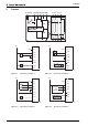
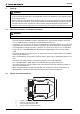
Function 3 Function A1 (+24V) ~ 13 23 33 41 S33 S34 S35 S31 S22 + = CH1 K1 MSI- SR4 0V 0V MSI-SR4 +24V 14 24 34 42 S12 A2 (0V) N.O. K2 N.O. N.O. CH2 MSI-SR4 +24V A1 A1 S22 S22 S12 S12 S31 S31 S33 S33 S34 S34 K4 K5 S35 S35 A2 A2 2 1 Figure 3.1: Connection example 1 0V Figure 3.2: 0V MSI-SR4 AOPD, Type 4 OSSD1 OSSD2 +24V Connection example 2 MSI-SR4 +24V A1 S22 A1 S22 AOPD, Type 4 S12 S12 S31 S31 +24V S33 S33 S34 S34 K4 S35 A2 K5 S35 A2 3 Figure 3.
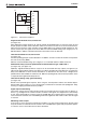
Function 0V MSI-SR4 closed open +24V A1 S22 S12 S31 S33 S34 S35 A2 5 Figure 3.5: Connection example 5 Single-channel E-STOP circuit, manual start (see figure 3.1) After applying the supply voltage to A1 and A2 and with the E-STOP button not actuated, relays K1 and K2 pick up upon actuation of the start button and lock. The release circuits 13-14, 23-24 and 33-34 close, signal circuit 41-42 opens. Upon actuation of the E-STOP button, K1 and K2 go dead and drop out.
Function Start button monitoring during manual start (see figure 3.1), (see figure 3.2), (see figure 3.3) To detect static faults or blocking of the start button, the button function is monitored for signal changes. Enabling occurs when the button is released (1/0 signal change). During automatic start (see e.g. figures 3.4, 3.5), this function is deactivated. Contactor monitoring (EDM) with manual start (see figure 3.
Start-up 4 Start-up WARNING ª Prior to the initial start-up on a power-driven machine, a competent person must inspect the connection of the connected protective device at the MSI-SR4 as well as the integration of the complete system in the machine control. ª Before switching on the supply voltage for the first time, it must be ensured that the outputs of the MSI have no effect on the machine.
Start-up 4.3 Tests The test prior to the first start-up as well as regular tests by competent persons are intended to ensure that the protective devices and any other protective components are correctly selected and provide the required protection when properly used acc. to the local regulations, particularly the machinery and work equipment directive (and, in Germany, the Ordinance on Industrial Safety and Health (Betriebssicherheitsverordung - BetrSichV) as well).
Technical data MSI-SR4 5 Technical data MSI-SR4 Category acc. to EN ISO 13849-1: 2009 4 Performance Level (PL) in accordance with EN ISO 13849-1 PL e Average probability of a failure to danger per 2.0 x 10⁻⁸ hour (PFHd) B10d DC 13: 10.0 million switching cycles AC 15: 1.4 million switching cycles Mean time to dangerous failure (MTTFd) 73 years Service life (TM) 20 years Stop category Stop 0 acc.
Technical data MSI-SR4 Connection cross-sections 1 x 0.2 to 2.5 mm2, fine-wired or 1 x 0.25 to 2.5 mm2, fine-wired with wire-end sleeves 2 x 0.5 to 1.5 mm2, fine-wired with Twin wire-end sleeves 1 x 0.2 to 2.5 mm2, single-wired or 2 x 0.25 to 1.0 mm2, fine-wired with wire-end sleeves 2 x 0.2 to 1.5 mm2, fine-wired 2 x 0.2 to 1.0 mm2, single-wired Dimensions (H x W x D) 99 x 22.5 x 111.5 mm Weight 170 g Order No.
Technical data MSI-SR4 You can download thisEC Declaration of Conformity as a PDF from: http://www.leuze.