MS-7093 (v1.
Manual Rev: 1.3 Release Date: Nov. 2004 FCC-B Radio Frequency Interference Statement This equipment has been tested and found to comply with the limits for a class B digital device, pursuant to part 15 of the FCC rules. These limits are designed to provide reasonable protection against harmful interference when the equipment is operated in a commercial environment.
Copyright Notice The material in this document is the intellectual property of MICRO-STAR INTERNATIONAL. We take every care in the preparation of this document, but no guarantee is given as to the correctness of its contents. Our products are under continual improvement and we reserve the right to make changes without notice. Trademarks All trademarks are the properties of their respective owners. Intel ® and Pentium® are registered trademarks of Intel Corporation.
Safety Instructions 1. Always read the safety instructions carefully. 2. Keep this User’s Manual for future reference. 3. Keep this equipment away from humidity. 4. Lay this equipment on a reliable flat surface before setting it up. 5. The openings on the enclosure are for air convection hence protects the equipment from overheating. DO NOT COVER THE OPENINGS. 6. Make sure the voltage of the power source and adjust properly 110/220V before connecting the equipment to the power inlet. 7.
CONTENTS FCC-B Radio Frequency Interference Statement .......................................................... ii Copyright Notice ............................................................................................................ iii Trademarks .................................................................................................................... iii Revision History ............................................................................................................
Getting Started Chapter 1. Getting Started Getting Started Thank you for choosing the MS-7093 v1.X Micro ATX mainboard. The MS-7093 mainboard is based on ATi® RX480 & SB400 chipsets for optimal system efficiency. Designed to fit the advanced AMD® K8 Athlon 64 FX processor, the MS-7093 mainboard delivers a high performance and professional desktop platform solution.
MS-7093 M-ATX Mainboard Mainboard Specifications CPU h Supports Socket-939 for AMD K8 Athlon 64 FX processor h Supports Newcastle:4000 + and above Claw Hammer: 3000+, 3200+ and 3400+ and 3700+ Sempron: 3100+ and above (For the latest information about CPU, please visit http://www.msi.com.tw/program/products/mainboard/mbd/pro_mbd_cpu_support.
Getting Started MSI Reminds You... 1. Please note that users cannot install OS, either WinME or Win98, in their SATA hard drives. Under these two OSs, SATA can only be used as an ordinary storage device. 2. To create a bootable RAID volume for a Windows 2000 environment, Microsoft’s Windows 2000 Service Pack 4 (SP4) is required. As the end user cannot boot without SP4, a combination installation CD must be created before attempting to install the operating system onto the bootable RAID volume.
MS-7093 M-ATX Mainboard - 4 serial ATA ports - 2 IEEE1394s (Rear * 1 / Front * 1) BIOS h The mainboard BIOS provides “Plug & Play” BIOS which detects the peripheral devices and expansion cards of the board automatically. h The mainboard provides a Desktop Management Interface (DMI) function which records your mainboard specifications. h Supports boot from LAN, USB Device 1.1 & 2.0, and SATA HDD. Dimension h Micro-ATX Form Factor: 24.4cm X 24.
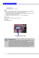
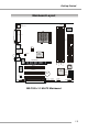
Getting Started Mainboard Layout CFAN1 Top: Mouse Bottom: Keyboard FDD1 SMSC LPC47M997-NR ATX1 Parallel Port T: 1394 Port B: USB Ports JPW1 BIOS DIMM3 DIMM4 DIMM1 PCI 1 DIMM2 PCIE16X1 VIA VT6307 PCI 2 ALC658 Codec IDE 1 ATI RX480 SFAN1 SPDIF-Out T: Line-In M: Line-Out B: Mic Realtek 8100C IDE 2 T: LAN Jack B: USB Ports PCI 3 ATI SB400 BATT + SATA1 SATA2 SATA3 JCOMS1 SATA4 JCD1 J1394_1 JUSB1 JUSB2 JFP1 JAUD1 JPWD1 JAUX1 MS-7093 v1.
Hardware Setup Chapter 2. Hardware Setup Hardware Setup This chapter tells you how to install the CPU, memory modules, and expansion cards, as well as how to setup the jumpers on the mainboard. Also, it provides the instructions on connecting the peripheral devices, such as the mouse, keyboard, etc. While doing the installation, be careful in holding the components and follow the installation procedures.
MS-7093 M-ATX Mainboard Central Processing Unit: CPU The mainboard supports AMD ® Athlon64 processor. The mainboard uses a CPU socket called Socket-939 for easy CPU installation. When you are installing the CPU, make sure the CPU has a heat sink and a cooling fan attached on the top to prevent overheating. If you do not have the heat sink and cooling fan, contact your dealer to purchase and install them before turning on the computer. For the latest information about CPU, please visit http://www.msi.com.
Hardware Setup CPU Installation Procedures for Socket 939 1. Please turn off the power and unplug the power cord before installing the CPU. Open Lever Sliding Plate 90 degree 2. Pull the lever sideways away from the socket. Make sure to raise the lever up to a 90-degree angle. Gold arrow 3. Look for the gold arrow. The gold arrow should point towards the lever pivot. The CPU can only fit in the correct orientation. 4.
MS-7093 M-ATX Mainboard Installing AMD Athlon64 CPU Cooler Set When you are installing the CPU, make sure the CPU has a heat sink and a cooling fan attached on the top to prevent overheating. If you do not have the heat sink and cooling fan, contact your dealer to purchase and install them before turning on the computer. MSI Reminds You... Mainboard photos shown in this section are for demonstration of the cooler installation for Socket 939 CPUs only.
Hardware Setup 5. Position the cooling set onto the retention mechanism. 7. Fasten down the lever. Hook one end of the clip to hook first, and then press down the other end of the clip to fasten the cooling set on the top of the retention mechanism. 8. Make sure the safety hook completely clasps the fixed bolt of the retention mechanism. 6. Locate the Fix Lever, Safety Hook and the Fixed Bolt. Lift up the intensive fixed lever. 9. Attach the CPU Fan cable to the CPU fan connector on the mainboard.
MS-7093 M-ATX Mainboard Memory The mainboard provides 4 slots for 184-pin DDR DIMM (Double In-Line Memory Module) modules and supports the memory size up to 4GB. You can install DDR 333/ 400 modules on the DDR DIMM slots (DIMM 1~4). DIMM1~DIMM4 (from left to right) Memory Population Rules Install at least one DIMM module on the slots. Each DIMM slot supports up to a maximum size of 1GB. Users can install either single- or double-sided modules to meet their own needs.
Hardware Setup Installing DDR Modules 1. 2. 3. The DDR DIMM has only one notch on the center of module. The module will only fit in the right orientation. Insert the DIMM memory module vertically into the DIMM slot. Then push it in until the golden finger on the memory module is deeply inserted in the socket. The plastic clip at each side of the DIMM slot will automatically close.
MS-7093 M-ATX Mainboard Power Supply The mainboard supports ATX power supply for the power system. Before inserting the power supply connector, always make sure that all components are installed properly to ensure that no damage will be caused. ATX 24-Pin Power Connector: ATX1 This connector allows you to connect an ATX 24-pin power supply. To connect the ATX 24-pin power supply, make sure the plug of the power pin 13 supply is inserted in the proper orientation and the pins are aligned.
Hardware Setup Back Panel L-In Parallel Mouse LAN 1394 Port Keyboard USB Ports Mouse/Keyboard Connector SPDIF-Out L-Out Mic USB Ports Pin5 Mouse/KBD Clock Pin6 NC Pin4 VCC Pin3 GND 1 2 3 PIN 1 2 3 4 4 Pin1 Mouse/KBD DATA Pin2 NC SIGNAL VCC -Data +Data GND RJ-45 LAN Jack IEEE 1394 Port 2 4 6 1 3 5 8 1 10/100 LAN PIN SIGNAL DESCRIPTION Transmit Differential Pair PIN SIGNAL 1 TDP 1 2 3 4 5 6 PWR GND TPBTPB+ TPATPA+ 2 TDN Transmit Differential Pair 3 RDP Receive Diff
MS-7093 M-ATX Mainboard Connectors Floppy Disk Drive Connector: FDD1 The mainboard provides a standard floppy disk drive connector that supports 360K, 720K, 1.2M, 1.44M and 2.88M floppy disk types. FDD1 Fan Power Connectors: CFAN1 / SFAN1 The fan power connectors support system cooling fan with +12V. When connecting the wire to the connectors, always take note that the red wire is the positive and should be connected to the +12V, the black wire is Ground and should be connected to GND.
Hardware Setup ATA100 Hard Disk Connectors: IDE1 & IDE2 The mainboard has a 32-bit Enhanced PCI IDE and Ultra DMA 66/100 controller that provides PIO mode 0~4, Bus Master, and Ultra DMA 66/100 function. You can connect up to four hard disk drives, CD-ROM and other IDE devices. The Ultra ATA100 interface boosts data transfer rates between the computer and the hard drive up to 100 megabytes (MB) per second.
MS-7093 M-ATX Mainboard Serial ATA Connectors: SATA1~SATA4 The ATI SB400 SouthBridge supports four serial ATA connectors SATA1~SATA4. SATA1~SATA4 are high-speed Serial ATA interface ports. Each supports 1st generation serial ATA data rates of 150MB/s and is fully compliant with Serial ATA 1.0 specifications. Each Serial ATA connector can connect to 1 hard disk device.
Hardware Setup Front Panel Audio Connector: JAUD1 The JAUD1 front panel audio connector allows you to connect to the front panel audio and is compliant with Intel® Front Panel I/O Connectivity Design Guide.
MS-7093 M-ATX Mainboard CD-In Connector: JCD1 This connector is provided for CD-ROM audio. Aux Line-In Connector: JAUX1 The connector is for DVD add-on card with Line-in connector. JCD1 JAUX1 R GND L R GND L IEEE 1394 Connectors: J1394_1 The mainboard provides one 1394 pin header that allows you to connect IEEE 1394 ports via an external IEEE1394 bracket.
Hardware Setup Front Panel Connectors: JFP1 The mainboard provides one front panel connector for electrical connection to the front panel switches and LEDs. The JFP1 is compliant with Intel® Front Panel I/O Connectivity Design Guide.
MS-7093 M-ATX Mainboard Jumpers The motherboard provides the following jumpers for you to set the computer’s function. This section will explain how to change your motherboard’s function through the use of jumpers. Clear BIOS Password Jumper: JPWD1 The jumper is used to clear the BIOS password. To clear the password, open the jumper and restart your computer.
Hardware Setup Slots The motherboard provides one PCI Express x16 slot, three 32-bit PCI bus slots, and one SCSI connector for PCI Extender Card. PCI Express x16 slot PCI Slots SCSI Connector PCI Express Slots The PCI Express slot, as a high-bandwidth, low pin count, serial, interconnect technology, supports Intel highest performance desktop platforms utilizing the Intel Pentium 4 processor with HT Technology.
MS-7093 M-ATX Mainboard PCI Interrupt Request Routing The IRQ, acronym of interrupt request line and pronounced I-R-Q, are hardware lines over which devices can send interrupt signals to the microprocessor.