5520 Master Series MS-91C2 (V1.X) Server Board G52-91C21X1 i PDF created with pdfFactory Pro trial version www.pdffactory.
Copyright Notice T he material in this doc ument is the intellec tual property of M ICRO-STAR INTERNATIONAL. We take every care in the preparation of this document, but no guarantee is given as to the correctness of its contents. Our products are under continual improvement and we reserve the right to make changes without notice. Trademarks All trademarks are the properties of their respective owners.
Safety Instructions 1. Always read the safety instructions carefully. 2. Keep this User’s Manual for future reference. 3. Keep this equipment away from humidity. 4. Lay this equipment on a reliable flat surface before setting it up. 5. The openings on the enclosure are for air convection hence protects the equipment from overheating. DO NOT COVER THE OPENINGS. 6. Make sure the voltage of the power source and adjust properly 110/220V before connecting the equipment to the power inlet. 7.
FCC-B Radio Frequency Interference Statement T h is eq uip men t h as been tested and found to c omply with the limits for a Class B digital device, pursuant to Part 15 of the FCC Rules. These limits are designed to provide reasonable protection against harmful interference in a residential installation. This equipment generates, uses and can radiate radio frequency energy and, if not installed and used in accordance with the instructions, may cause harmful interference to radio communications.
WEEE (Waste Electrical and Electronic Equipment) Statement v PDF created with pdfFactory Pro trial version www.pdffactory.
vi PDF created with pdfFactory Pro trial version www.pdffactory.
vii PDF created with pdfFactory Pro trial version www.pdffactory.
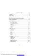
CONTENTS Copyright Notice .............................................................................................................. ii Trademarks ....................................................................................................................... ii Revision History .............................................................................................................. ii Technical Support .........................................................................................
Getting Started Chapter 1 Getting Started Thank you for choosing the 5520 Master Series (MS91C2 V1.X), an excellent server board from MSI. Based on the innovative Intel® 5520 & ICH10R chipsets for optimal system efficiency, the 5520 Master Series accommodate the latest 45nm Intel® Gainstown/Nehalem processors in LGA1366 package and support up to 12 DDR3 800/1066/1333 DIMM slots to provide the maximum of 96GB memory capacity.
M S-91C2 Server Board Mainboard Specifications Proce ssor - 45nm Intel Gainstown/Nehalem processors in LGA1366 package Supported QPI - Up to 6.
Getting Started Onboard I/O Back Panel - 1 serial console port (RJ-45 jack) 2 USB 2.0 ports 2 Gigabit LAN jacks 1 VGA port 2 InfiniBand connectors Onboard Connectors - 2 USB 2.0 pinheaders (4 ports) - 1 serial port connector - 2 SMBus pinheaders Slot - 1 PCI Express x16 slot Dimension - 6.5” x 17.9” M ounting - 5 mounting holes 1-3 PDF created with pdfFactory Pro trial version www.pdffactory.
M S-91C2 Server Board Mainboard Layout 5520 Master Series (MS-91C2 V1.X) Server Board 1-4 PDF created with pdfFactory Pro trial version www.pdffactory.
Hardware Setup Chapter 2 Hardware Setup This chapter provides you with the information about hardware setup procedures. While doing the installation, be careful in holding the components and follow the installation procedures. For some components, if you install in the wrong orientation, the components will not work properly. Use a grounded wrist strap before handling computer c om ponen ts . S tatic elec tric ity m ay damage the components. 2-1 PDF created with pdfFactory Pro trial version www.
M S-91C2 Server Board Quick Components Guide FAN1, p.2-11 FAN2, p.2-11 FAN3, p.2-11 DIMM Slots, p.2-7 JPWR1, p.2-8 JPWR3, p.2-8 JPWR2, p.2-8 CPU, p.2-3 DIMM Slots, p.2-7 CPU, p.2-3 JFP1, p.2-13 J_SMBUS1, p.2-14 JUSB1~2, p.2-12 SATA1~4, p.2-10 FAN4, p.2-11 PCIE_SLOT1, p.2-16 JBAT1, p.2-15 J_SMLINK1, p.2-14 COM2, p.2-11 J_IPMB1, p.2-13 Back Panel I/O, p.2-9 J_BMC_WP1, p.2-15 2-2 PDF created with pdfFactory Pro trial version www.pdffactory.
Hardware Setup CPU (Central Processing Unit) W hen you are installing the CPU, make sure that you install the cooler to prevent the CPU from overheating. If you do not have the CPU cooler, consult your dealer before turning on the computer. Important Overheating Overheating will seriously damage the CPU and system. Always make sure the cooling fan can work properly to protect the CPU from overheating.
M S-91C2 Server Board CPU & Cooler Installation W hen you are installing the CPU, make sure the CPU has a cooler attached on the top to prevent overheating. Meanwhile, do not forget to apply some thermal paste on CPU before installing the heat sink/cooler fan for better heat dispersion. Follow the steps below to install the CPU & cooler correctly. W rong installation will cause the damage of your CPU & mainboard. 1. Open the load lever. 2. Lift the load lever up and open the load plate. 3.
Hardware Setup 5. Visually inspect if the CPU is seated well into the socket. If not, take out the CPU with pure vertical motion and reinstall. 6. C over t h e l oad p l at e on t o t h e package. 7. Press down the load lever lightly onto the load plate, and then secure the lever with the hook under retention tab. 8. Align the holes on the mainboard with the heatsink. Push down the cooler until its four clips get wedged into the holes of the mainboard. Important 1.
M S-91C2 Server Board 9. Align the holes on the mainboard with the heatsink. Push down the cooler until its four clips get wedged into the holes of the mainboard. 10. Turn over the mainboard to confirm that the c lip-ends are c orrectly inserted. Mainboard Hook Important 1. Read the CPU status in BIOS. 2. Whenever CPU is not installed, always protect your CPU socket pin with the plastic cap covered (shown in Figure 1) to avoid damaging. 3.
Hardware Setup Memory These DIMM slots are intended for system memory modules. DDR3 240-pin, 1.5V 48x2=96 pin 72x2=144 pin Installing Memory Modules 1. Locate the DIMM slots on the mainboard. Flip open the retaining clip at each side of the DIMM slot. 2. Align the notch on the DIMM with the key on the slot. Insert the DIMM vertically into the DIMM slot. Then push it in until the golden finger on the DIMM is deeply inserted in the DIMM slot.
M S-91C2 Server Board Power Supply 20-Pin System Power Connector: JPWR1, JPWR3 This connector allows you to connect to a power supply. To connect the power supply, make sure the plug of the power supply is inserted in the proper orientation and the pins are aligned. Then push down the power supply firmly into the connector.
Hardware Setup Back Panel I/O Serial Console Port LAN USB Ports VGA Port InfiniBand Connectors Serial Console Port The serial port is a 16550A high speed communications port that sends/ receives 16 bytes FIFOs. You can attach a serial mouse or other serial devices directly to the connector. USB Port The USB (Universal Serial Bus) port is for attaching USB devices such as keyboard, mouse, or other USB-compatible devices. VGA Port The DB15-pin female connector is provided for monitor.
M S-91C2 Server Board Connector Serial ATA Connector: SATA1 ~ SATA4 This connector is a high-speed Serial ATA interface port. Each connector can connect to one Serial ATA device. SATA1 SATA2 SATA3 SATA4 Important Please do not fold the Serial ATA cable into 90-degree angle. Otherwise, data loss may occur during transmission. 2-10 PDF created with pdfFactory Pro trial version www.pdffactory.
Hardware Setup Serial Port Connector: COM2 This connector is a 16550A high speed communications port that sends/receives 16 bytes FIFOs. You can attach a serial device to it through the optional serial port bracket.
M S-91C2 Server Board Front USB Connector: JUSB1, JUSB2 This connector, compliant with Intel® I/O Connectivity Design Guide, is ideal for connecting high-speed USB interface peripherals such as USB HDD, digital cameras, M P3 players, printers, modems and the like. Pin Definition JUSB1, JUSB2 9 10 1 2 PIN SIGNAL PIN SIGNAL 1 VCC 2 VCC 3 USB0- 4 USB1- 5 USB0+ 6 USB1+ 7 GND 8 GND 9 Key (no pin) 10 USBOC USB 2.
Hardware Setup IPMB Connector: J_IPMB1 This connector is used to connect the IPMB (Intelligent Platform Management Bus) SMBus. Pin Definition J_IPMB1 1 3 PIN SIGNAL 1 2 IPMB_DATA GND 3 IPMB_CLK Front Panel Connector: JFP1 This connector is designed for electrical connection to the front panel switches and LEDs.
M S-91C2 Server Board I2C Bus Connector: J_SMBUS1, J_SMLINK1 This connector, known as I 2C, is for users to connect System Management Bus (SMBus) interface. J_SMBUS1 Pin Definition J_SMBUS1 1 J_SMLINK1 1 PIN SIGNAL 1 2 SMBUS_ICH_DATA SMBUS_ICH_CLK 3 SMBUS_ALERT# J-SMLINK1 Pin Definition PIN SIGNAL 1 SM_LINK1 2 3 SM_LINK0 LINK_ALERT# 2-14 PDF created with pdfFactory Pro trial version www.pdffactory.
Hardware Setup Jumper BMC Flash Jumper: J_BMC_WP1 This jumper is used to enable/disable the BMC flash. W hen you intend to update the BMC code, uncap this jumper first. Under normal operation, we suggest that you disable the BMC flash by capping this jumper to protect the BMC from virus infection. J_BMC_WP1 Disable BMC Flash Enable BMC Flash Clear CMOS Jumper: JBAT1 There is a CMOS RAM onboard that has a power supply from an external battery to keep the data of system configuration.
M S-91C2 Server Board Slot PCI (Peripheral Component Interconnect) Express Slot The PCI Express slot supports the PCI Express interface expansion card. The PCI Express x16 slot supports up to 4.0 GB/s transfer rate. PCI Express x16 Slot Important When adding or removing expansion cards, make sure that you unplug the power supply first.
BIOS Setup Chapter 3 BIOS Setup This chapter provides information on the BIOS Setup program and allows you to configure the system for optimum use. You may need to run the Setup program when: ² An error message appears on the screen during the system booting up, and requests you to run SETUP. ² You want to change the default settings for customized features. 3-1 PDF created with pdfFactory Pro trial version www.pdffactory.
M S-91C2 Server Board Entering Setup Power on the computer and the system will start POST (Power On Self Test) process. W hen the message below appears on the screen, press key to enter Setup. Press Del to enter SETUP If the message disappears before you respond and you still wish to enter Setup, restart the system by turning it OFF and On or pressing the RESET button. You may also restart the system by simultaneously pressing , , and keys. Important 1.
BIOS Setup Control Keys < -> Move to the previous item < ¯> Move to the next item < ¬> Move to the item in the left hand < ®> Move to the item in the right hand Select the item Jumps to the Exit menu or returns to the main menu from a submenu <+/PU> Increase the numeric value or make changes <-/PD> Decrease the numeric value or make changes Load Optimized Defaults Load Fail-Safe Defaults Save all the CMOS changes and exit Getting Help After entering the S
M S-91C2 Server Board The Menu Bar Main Use this menu for basic system configurations, such as time, date etc. Advanced Use this menu to set up the items of special enhanced features. Boot Use this menu to specify the priority of boot devices. Security Use this menu to set supervisor and user passwords. Chipset This menu controls the advanced features of the onboard Northbridge and Southbridge.
BIOS Setup Main AM I BIOS, Processor, System M emory These items show the firmware and hardware specifications of your system. Read only. System Time This setting allows you to set the system time. The time format is . System Date This setting allows you to set the system date. The date format is , . 3-5 PDF created with pdfFactory Pro trial version www.pdffactory.
M S-91C2 Server Board Advanced CPU Configuration C1E Support W hen the C1E Support (Enhanced Halt Powerdown State) is enabled, the processor will transition to a lower core to bus ratio and lower voltage ID driven by 3-6 PDF created with pdfFactory Pro trial version www.pdffactory.
BIOS Setup the processor to the voltage regulator before entering Halt Powerdown State (C1). Not all porcessors support Enhanced Halt Powerdown State (C1E). Hardware Prefetcher The processor has a hardware prefetcher that automatically analyzes its requirements and prefetches data and instructions from the memory into the Level 2 cache that are likely to be required in the near future. This reduces the latency associated with memory reads.
M S-91C2 Server Board Intel(R) TurboM ode Tech This item is used to enable/ disable Intel Robson technology. Intel Robson technology is turbo memory technology that can let the users to enable operation system without accessing hard disk frequenctly. This boot up way can promote 20% speed and promote the speed of the large application program two times that can speed up the enable time and reduce power consumption.
BIOS Setup 1st/ 2nd/ 3rd/ 4th IDE [Type] Press PgUp/<+> or PgDn/<-> to select [Manual], [None] or [Auto] type. Note that the specifications of your drive must match with the drive table. The hard disk will not work properly if you enter improper information for this category. If your hard disk drive type is not matched or listed, you can use [Manual] to define your own drive type manually.
M S-91C2 Server Board Super IO Configuration Serial Port 1 Address, Serial Port 2 Address Select an address and a corresponding interrupt for the serial port 1/2. ACPI Configuration 3-10 PDF created with pdfFactory Pro trial version www.pdffactory.
BIOS Setup Advanced ACPI Configuration ACPI Version Features This setting allows you to select the ACPI version. ACPI APIC Support This BIOS feature is used to enable or disable the motherboard's APIC (Advanced Programmable Interrupt Controller). The APIC provides multiprocessor support, more IRQs and faster interrupt handling. AMI OEM B Table OEMB table is used to pass Disabled POST data to the AML code during ACPI O/S operations.
M S-91C2 Server Board Chipset ACPI Configuration High Performance Event Timer The High Precision Event Timer (HPET) was developed jointly by Intel and Microsoft to meet the timing requirements of multimedia and other time-sensitive applications. In addition to extending the capabilities and precision of a system, the HPET also improves system performance. HPET M emory Address This setting specifies the HPET memory address. AHCI Configuration 3-12 PDF created with pdfFactory Pro trial version www.
BIOS Setup AHCI BIOS Support This BIOS feature controls the SATA controller's AHCI (Advanced Host Controller Interface) functionality. It is a new interface specification that enables advanced SATA features like Native Command Queuing (NCQ) and hot-plugging. AHCI CD/DVD Boot Time Out This setting specifies the delay of the AHCI CD/DVD drivers loading for multiread/write. Changing the value to 0 will grant no delay at boot. AHCI Port 0/1/2/3 SATA Port 0 This setting controls the SATA port 0. S.M.A.R.T.
M S-91C2 Server Board IPMI 2.0 Configuration Status of BM C, BM C Firmware Version These settings show the status of the BMC (Baseboard Management Controller) chip and its firmware version. Read only. View BM C System Event Log Use this function to view system event logs recorded by BMC. Clear BM C System Event Log Use this function to clear system event logs recorded by BMC. 3-14 PDF created with pdfFactory Pro trial version www.pdffactory.
BIOS Setup BM C LAN1/ LAN2 Configuration Notify BMC IP Source Use this setting to check the BMC IP source. Current IP Address in BMC, Current Subnet Mask in BM C, Current Gateway in BM C Use these settings to view the IP address, subnet mask, and gateway in BMC. Hardware Health Information These items display the current status of all of the monitored hardware devices/components such as voltages, temperatures and all fans’ speeds. 3-15 PDF created with pdfFactory Pro trial version www.pdffactory.
M S-91C2 Server Board FAN Control Type This item enables/disables the Smart Fan feature. Smart Fan is an excellent feature which will adjust the CPU fan speed automatically depending on the CPU current temperature, avoiding the overheating to damage your system. Remote Access Configuration Remote Access The setting enables/disables the remote access function. W hen set to [Enabled], us ers may c onfigure the f ollowing s ettings f or remote ac cess type and parameters.
BIOS Setup host system and terminal(s). This setting specifies the type of terminal device for console redirection. VT-UTF8 Combo Key Support This setting enables/disables the VT-UTF8 combination key support for ANSI/ VT100 terminals. Sredir Memory Display Delay Use this setting to set the delay in seconds to display memory information. APM Configuration Resume On RTC Alarm W hen [Enabled], your can set the date and time at which the RTC (real-time clock) alarm awakens the system from suspend mode.
M S-91C2 Server Board Boot Boot Settings Configuration 3-18 PDF created with pdfFactory Pro trial version www.pdffactory.
BIOS Setup Quiet Boot This BIOS feature determines if the BIOS should hide the normal POST messages with the motherboard or system manufacturer's full-screen logo. W hen it is enabled, the BIOS will display the full-screen logo during the boot-up sequence, hiding normal POST messages. When it is disabled, the BIOS will display the normal POST messages, instead of the full-screen logo. Please note that enabling this BIOS feature often adds 2-3 seconds of delay to the booting sequence.
M S-91C2 Server Board Security Supervisor Password / Change Supervisor Password Supervisor Password controls access to the BIOS Setup utility. These settings allow you to set or change the supervisor password. User Password / Change User Password User Password controls access to the system at boot. These settings allow you to set or change the user password.
BIOS Setup Chipset CPU Bridge Configuration QPI Links Speed This item allows you to select the QPI links speed type. 3-21 PDF created with pdfFactory Pro trial version www.pdffactory.
M S-91C2 Server Board QPI Frequency This item allows you to select the QPI frequency. M emory Frequency This setting allows you to select the memory frequency. M emory M ode This setting specifies the memory mode. Demand Scrubbing, Patrol Scrubbing These settings support demand and patrol scrubbing to detect and repair memory problems. If it encounters a memory problem that cannot be repaired, it marks the bad location so that it will not be used in the future.
BIOS Setup North Bridge Information This sub-menu shows the north bridge information. South Bridge Configuration USB Functions This setting specifies the function of the onboard USB controller. 3-23 PDF created with pdfFactory Pro trial version www.pdffactory.
M S-91C2 Server Board Restore on AC Power Loss This setting specifies whether your system will reboot after a power failure or interrupt occurs. Available settings are: [Power Off] Leaves the computer in the power off state. [Power On] Leaves the computer in the power on state. [Last State] Restores the system to the previous status before power failure or interrupt occurred. 3-24 PDF created with pdfFactory Pro trial version www.pdffactory.
BIOS Setup Exit Save Changes and Exit Save changes to CMOS and exit the Setup Utility. Discard Changes and Exit Abandon all changes and exit the Setup Utility. Discard Changes Abandon all changes and continue with the Setup Utility. Load Optimal Defaults Use this menu to load the default values set by the mainboard manufacturer specifically for optimal performance of the mainboard. Load Failsafe Defaults Use this menu to load the default values set by the BIOS vendor for stable system performance.
This page is intentionally left blank. viii PDF created with pdfFactory Pro trial version www.pdffactory.
Intel ICH10R SATA RAID Appendix A Intel ICH10R SATA RAID This appendix will assist users in configuring and enabling RAID functionality on platforms A-1 PDF created with pdfFactory Pro trial version www.pdffactory.
M S-91C2 Server Board Introduction The ICH10R provides a hybrid solution that combines 6 independent SATAII ports for support of up to 6 Serial ATAII (Serial ATAII RAID) drives. Serial ATAII (SATAII) is the latest generation of the ATA interface. SATA hard drives deliver blistering transfer speeds up to 3 Gb/s. Serial ATA uses long, thin cables, making it easier to connect your drive and improving the airflow inside your PC. The most outstanding features are: 1.
Intel ICH10R SATA RAID BIOS Configuration The Intel Matrix Storage Manager Option ROM should be integrated with the system BIOS on all motherboards with a supported Intel chipset. The Intel Matrix Stroage Manager Option ROM is the Intel RAID implementation and provides BIOS and DOS disk services. Please use + keys to enter the “Intel(R) RAID for Serial ATA” status screen, which should appear early in system boot-up, during the POST (Power-On Self Test).
M S-91C2 Server Board After pressing the and keys simultaneously, the following window will appear: (1) Create RAID Volume 1. 2. Select option 1 “Create RAID Volume” and press key. The following screen appears. Then in the Name field, specify a RAID Volume name and then press the or key to go to the next field. Use the arrow keys to select the RAID level best suited to your usage model in RAID Level. A-4 PDF created with pdfFactory Pro trial version www.pdffactory.
Intel ICH10R SATA RAID 3. In the Disk field, press key and the following screen appears. Use key to select the disks you want to create for the RAID volume, then click key to finish selection. 4. Then select the strip value for the RAID array by using the “upper arrow” or “down arrow” keys to scroll through the available values, and pressing the key to select and advance to the next field. The available values range from 4KB to 128 KB in power of 2 increments.
M S-91C2 Server Board Important Since you want to create two volumes (Intel Matrix RAID Technology), this default size (maximum) needs to be reduced. Type in a new size for the first volume. As an example: if you want the first volume to span the first half of the two disks, re-type the size to be half of what is shown by default. The second volume, when created, will automatically span the remainder of two hard drives. 6.
Intel ICH10R SATA RAID (2) Delete RAID Volume Here you can delete the RAID volume, but please be noted that all data on RAID drives will be lost. Important If your system currently boots to RAID and you delete the RAID volume in the Intel RAID Option ROM, your system will become unbootable. Select option 2 Delete RAID Volume from the main menu window and press key to select a RAID volume for deletion. Then press key to delete the selected RAID volume. The following screen appears.
M S-91C2 Server Board (3) Reset Disks to Non-RAID Select option 3 Reset Disks to Non-RAID and press to delete the RAID volume and remove any RAID structures from the drives. The following screen appears: Press key to accept the selection. Important 1. You will lose all data on the RAID drives and any internal RAID structures when you perform this operation. 2.
Intel ICH10R SATA RAID (4) Recovery Volume Options Select option 4 Recovery Volume Options and press to change recovery volume mode. The following screen appears: Recovery mode will change from Continuous Update to On-Request after you enable “Only Recovery Disk” or “Only Master Disk”. A-9 PDF created with pdfFactory Pro trial version www.pdffactory.
M S-91C2 Server Board Installing Driver Install Driver in Windows Server 2008/2003 † New Windows Server 2008/2003 Installation The following details the installation of the drivers while installing operating system. 1. W hen you start installing W indows Server 2008/2003, you may encounter a message stating, “Setup could not determine the type of one or more mass storage devices installed in your system”. If this is the case, then you are already in the right place and are ready to supply the driver.
Intel ICH10R SATA RAID † Existing Windows Server 2008/2003 Driver Installation 1. Insert the MSI CD into the CD-ROM drive. 2. The CD will auto-run and the setup screen will appear. 3. Under the Server Drivers tab, click on SATA2 RAID Install. 4. The drivers will be automatically installed. † Confirming Windows Server 2008/2003 Driver Installation 1. Under W indows Server 2008/2003, open the Control Panel from My Computer followed by the System icon. 2.
M S-91C2 Server Board Installing Software Install Intel Matrix Storage Console The Intel Application Accelerator RAID Edition driver may be used to operate the hard drive from which the system is booting or a hard drive that contains important data. For this reason, you cannot remove or un-install this driver from the system after installation; however, you will have the ability to un-install all other non-driver components.
Intel ICH10R SATA RAID The InstallShield Wizard will begin automatically for installation showed as following: Click on the Next button to proceed the installation in the welcoming window. A-13 PDF created with pdfFactory Pro trial version www.pdffactory.
M S-91C2 Server Board The window shows the components to be installed. Click Next button to continue. After reading the license agreement in the following window, click Yes button to continue. A-14 PDF created with pdfFactory Pro trial version www.pdffactory.
Intel ICH10R SATA RAID The following window appears to show the Readme File Information. It shows the system requirements and installation information. Once the installation is complete, the following window appears. A-15 PDF created with pdfFactory Pro trial version www.pdffactory.
M S-91C2 Server Board RAID Migration Instructions The Intel Matrix Storage Console offers the flexibility to upgrade from a single Serial ATA (SATA) hard drive to RAID configuration when an additional SATA hard drive is added to the system. This process will create a new RAID volume from an existing disk. However, several important steps must be followed at the time the system is first configured in order to take advantage of RAID when upgrading to a second SATA hard drive: 1.
Intel ICH10R SATA RAID Create RAID Volume from Existing Disk To create a RAID volume from an existing disk, choose Action --> Create RAID Volume from Existing Hard Drive. The Create RAID Volume from Existing Hard Drive Wizard pops up to lead you for the following procedure. Click Next to continue. A-17 PDF created with pdfFactory Pro trial version www.pdffactory.
M S-91C2 Server Board (1) Configure Volume Here you can configure the new RAID volume by entering the volume name, selecting the RAID level and strip size. † RAID Volume Name: A desired RAID volume name needs to be typed in where the ‘Volume_0000’ text currently appears above. The RAID volume name has a maximum limit of 16 characters. The RAID volume name must also be in English alphanumeric ASCII characters.
Intel ICH10R SATA RAID expensive (requiring read-in prior to write, in order to be able to calculate the correct parity information), or similar to RAID-1 writes. The write efficiency depends heavily on the amount of memory in the machine, and the usage pattern of the array. Heavily scattered writes are bound to be more expensive. RAID 10 (Mirrored Stripes) – A RAID 1 array of two RAID 0 arrays. † Strip Sizes: Select the desired strip size setting. As indicated, the optimal setting is 128KB.
M S-91C2 Server Board (3) Select Member Hard Drive(s) Then select the member disk (the target disk) that you wish to use and then click “-->” to move it to the Selected field. Then click Next to continue. Please note that the existing data on the selected hard drive(s) will be deleted permanently. Do not forget to back up all the important data before continuing. A-20 PDF created with pdfFactory Pro trial version www.pdffactory.
Intel ICH10R SATA RAID (4) Specify Volume Size Specify the amount of available array space to be used by the new RAID volume. You may enter the amount in the space or use the slider to specify. It is recommended you use 100% of the available space for the optimized usage. For RAID 0 volume, if you do not specify 100% of the hard drive space, the rest hard drive space will be worked as RAID 1 volume, which is the new technology called Intel Matrix RAID. Then click Next to continue.
M S-91C2 Server Board (6) Start Migration The migration process may take up to two hours to complete depending on the size of the disks being used and the strip size selected. A dialogue window will appear stating that the migration process may take considerable time to complete, meanwhile a popup dialogue at the taskbar will also show the migration status. While you can still continue using your computer during the migration process, once the migration process starts, it cannot be stopped.
Intel ICH10R SATA RAID Recovery Volume Creation A recovery volume can be created using either Basic mode or Advanced mode in the Intel Matrix Storage Console. Recovery Volume in Basic Mode Creation Important Creating a recovery volume will permanently delete any existing data on the drive selected as the recovery drive. Back up all important data before beginning these steps. This option may or may not be available depending on your sy s tem configuration.
M S-91C2 Server Board Recovery Volume in Advanced Mode Creation Important Creating a recovery volume will permanently delete any existing data on the drive selected as the recovery drive. Back up all important data before beginning these steps. To create a recovery volume in Advanced mode, use the following steps: (1) Open the Intel Matrix Storage Console. (Start --> All Programs --> Intel Matrix Storage M anager --> Intel M atrix Storage Console) (2) Select Advanced Mode in the View menu.
Intel ICH10R SATA RAID (6) Select a hard drive to be used as the master hard drive for the recovery volume. (7) Select a hard drive to be used as the recovery hard drive for the recovery volume. A-25 PDF created with pdfFactory Pro trial version www.pdffactory.
M S-91C2 Server Board (8) Select an update policy. (9) Select Finish to begin recovery volume creation. A-26 PDF created with pdfFactory Pro trial version www.pdffactory.
Intel ICH10R SATA RAID Degraded RAID Array A RAID 1, RAID 5 or RAID 10 volume is reported as degraded when one of its hard drive members fails or is temporarily disconnected, and data mirroring is lost. As a result, the system can only utilize the remaining functional hard drive member. To reestablish data mirroring and restore data redundancy, refer to the procedure below that corresponds to the current situation. Missing Hard Drive Member 1. Make sure the system is powered off. 2.
M S-91C2 Server Board 5. Exit Intel RAID Option ROM, and then reboot to W indows system. 6. W hen prompted to rebuild the RAID volume, click 'Yes'. 7. The Intel(R) Storage Utility will be launched. Right-click the new hard drive and select 'Rebuild to this Disk'. The 'Rebuild W izard' will be launched which will guide you through the process of rebuilding to the new hard drive. A-28 PDF created with pdfFactory Pro trial version www.pdffactory.