
User`s manual


5-2
SUPERSERVER 6026TT-HT(R)F/HIBX(R)F/HIBQ(R)F USER'S MANUAL
5-2 Serverboard Installation
This section explains the first step of physically mounting the SuperServer
6026TT-HT(R)F/HIBX(R)F/HIBQ(R)F into the SC827H-(R)1400B chassis. Following
the steps in the order given will eliminate the most common problems encountered
in such an installation. To remove the serverboard, follow the procedure in reverse
order.
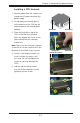
Accessing the Inside of the System
1. Remove all four screws securing the top cover of the chassis: two at the top
rear of the cover and one on each side lip, also near the back.
2. Place both thumbs in the indentations and push the cover back until it slides
off.
3. Lift the top cover from the chassis to gain full access to the inside of the
server. (If already installed in a rack, grasp the two handles on either side and
pull the unit straight out until the rails lock into place. See Figure 2-5.)
Check Compatibility of Serverboard Ports and I/O Shield
Make sure that the I/O ports on the serverboards align properly with their respective
holes in the I/O shield at the back of the chassis when installing.
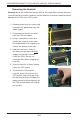
Mounting the Serverboard onto the Serverboard Tray
1. Carefully mount the serverboards by aligning the board holes with the raised
metal standoffs that are visible in the chassis.
2. Insert screws into all the mounting holes on your serverboards that line up
with the standoffs and tighten until snug (if you screw them in too tight, you
might strip the threads).
3. Metal screws provide an electrical contact to the serverboard ground to
provide a continuous ground for the system.
Warning: To avoid damaging the motherboard and its components, do not apply any
force greater than 8 lbs. per square inch when installing a screw into a mounting
hole.
5-3 Connecting Cables
Now that the serverboards are installed, the next step is to connect the cables to
the boards. These include the data cables for the peripherals and control panel
and the power cables.