
User`s manual
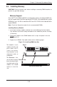

5-16
SUPERSERVER 6026TT-HT(R)F/HIBX(R)F/HIBQ(R)F USER'S MANUAL
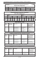
NIC2 (LAN2) LED
The LED connections for LAN2 are on
pins 9 and 10 of JF1. Attach LAN LED
cables to display network activity. See
the table on the right for pin defi nitions.
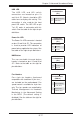
NIC1 LED
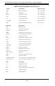
Pin Defi nitions
(JF1)
Pin# Defi nition
11 Vcc
12 Ground
NIC2 LED
Pin Defi nitions
(JF1)
Pin# Defi nition
9 Vcc
10 Ground
NIC1 (LAN1) LED
The LED connections for LAN1 are on
pins 11 and 12 of JF1. Attach LAN LED
cables to display network activity. See
the table on the right for pin defi nitions.
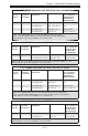
Overheat/Fan Fail/PWR Fail/UID LED
Pins 7 and 8 of JF1 are for the Overheat/
Fan Fail/Power Fail and UID LED
connections. The red LED (pin 8)
provides warnings of overheat, fan
failure or power failure. The blue LED
(pin 7) is for the UID LED indicator for
the control panel UID button. Refer to
the tables on the right for pin defi nitions.
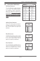
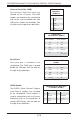
OH/Fan Fail/ PWR Fail/Blue_UID
LEDPin Defi nitions (JF1)
Pin# Defi nition
7 Blue UID LED/5.5V.SB
8 OH/Fan Fail/PWR Fail/Red UID LED
OH/Fan Fail/PWR Fail
LED Status (Red LED)
State Defi nition
Off Normal
On Overheat
Flashing Fan Fail
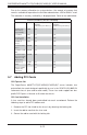
Power Fail LED
The Power Fail LED connection is
located on pins 5 and 6 of JF1. Refer to
the table on the right for pin defi nitions.
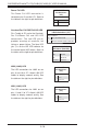
PWR Fail LED
Pin Defi nitions
(JF1)
Pin# Defi nition
5 3.3V
6 PWR Fail LED