
User`s manual
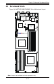

Chapter 5: Advanced Serverboard Setup
5-17
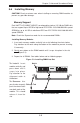
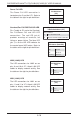
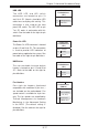
HDD LED
The HDD LED and UID switch
connections are located on pins 13
and 14 of JF1. Attach a hard drive LED
cable here to display disk activity. This
connection is also used for the front
panel UID switch. The UID LED on pin
7 of JF1 works in conjunction with this
switch. See the table on the right for pin
defi nitions.
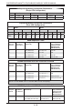
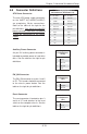
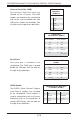
Fan Headers
Four 4-pin fan headers (backward
compatible with traditional 3-pin fans )
are included on the motherboard. Fan
speed control is available for 4-pin fans
only. The fan speeds are controlled by
Thermal Management via Hardware
Monitoring in the Advanced Setting
in the BIOS. (The default setting is
disabled.) See the table on the right for
pin defi nitions.
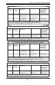
NMI Button
The non-maskable interrupt button
header is located on pins 19 and 20 of
JF1. Refer to the table on the right for
pin defi nitions.
NMI Button
Pin Defi nitions
(JF1)
Pin# Defi nition
19 Control
20 Ground
Fan Header
Pin Defi nitions
(FAN1-4)
Pin# Defi nition
1 Ground (Black)
2 +12V (Red)
3 Tachometer
4 PWM Control
Power On LED
The Power On LED connector is located
on pins 15 and 16 of JF1. This connection
is used to provide LED indication of
power being supplied to the system. See
the table on the right for pin defi nitions.
Power LED
Pin Defi nitions
(JF1)
Pin# Defi nition
15 5V Stby
16 Control
HDD LED
Pin Defi nitions
(JF1)
Pin# Defi nition
13 UID Signal/3.3V
14 HDD Active