Unpacking Thank you for buying the MSI® Z270 SLI PLUS/ Z270 SLI motherboard. Check to make sure your motherboard box contains the following items. If something is missing, contact your dealer as soon as possible.
Safety Information y The components included in this package are prone to damage from electrostatic discharge (ESD). Please adhere to the following instructions to ensure successful computer assembly. y Ensure that all components are securely connected. Loose connections may cause the computer to not recognize a component or fail to start. y Hold the motherboard by the edges to avoid touching sensitive components.
Quick Start Preparing Tools and Components Intel® LGA 1151 CPU CPU Fan DDR4 Memory Thermal Paste Power Supply Unit Chassis SATA DVD Drive Phillips Screwdriver SATA Hard Disk Drive Graphics Card A Package of Screws Quick Start 3
Installing a Processor 2 1 http://youtu.
Installing DDR4 memory http://youtu.
Connecting the Front Panel Header http://youtu.
Installing the Motherboard 1 2 Quick Start 7
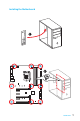
Installing SATA Drives http://youtu.
Installing a Graphics Card http://youtu.
Connecting Peripheral Devices 10 Quick Start
Connecting the Power Connectors http://youtu.
Power On 1 2 3 4 12 Quick Start
Contents Unpacking .............................................................................................................. 1 Safety Information ................................................................................................. 2 Quick Start ............................................................................................................. 3 Preparing Tools and Components .......................................................................... 3 Installing a Processor ......
JLPT1: Parallel Port Connector ........................................................................... 38 Onboard LEDs ...................................................................................................... 39 EZ Debug LEDs ..................................................................................................... 39 BIOS Setup ........................................................................................................... 40 Entering BIOS Setup ....................
Specifications CPU y Supports 7th/6th Gen Intel® Core™ i3/i5/i7 processors, and Intel® Pentium® and Celeron® processors for Socket LGA1151 Chipset Intel® Z270 Chipset y 4x DDR4 memory slots, support up to 64GB 7th processors support DDR4 3800(OC)/ 3600(OC)/ 3200(OC)/ 3000(OC)/ 2800(OC)/ 2600(OC)/ 2400/ 2133 MHz* Memory 6th processors support DDR4 3600(OC)/ 3200(OC)/ 3000(OC)/ 2800(OC)/ 2600(OC)/ 2400(OC)/ 2133 MHz* y Dual channel memory architecture y Supports non-ECC, un-buffered memory y Supports
Continued from previous page RAID Intel® Z270 Chipset y Supports RAID 0, RAID 1, RAID 5 and RAID 10 for SATA storage devices y Supports RAID 0 and RAID 1 for M.2 storage devices* * M.2 PCIe RAID volume can be created with M.2 GENIE. Please refer to page 43 for details about M.2 GENIE. y ASMedia® ASM2142 Chipset 1x USB 3.1 Gen2 (SuperSpeed USB 10Gbps) Type-C port on the back panel 1x USB 3.1 Gen2 (SuperSpeed USB 10Gbps) Type-A port on the back panel USB y Intel® Z270 Chipset 8x USB 3.
Continued from previous page y 1x Front panel audio connector y 2x Front panel connectors y 1x RGB LED connector (Z270 SLI PLUS) Internal Connectors y 1x TPM module connector y 1x Chassis Intrusion connector y 1x Serial port connector y 1x Parallel port connector y 1x Clear CMOS jumper I/O Controller NUVOTON NCT6795 Controller Chip y CPU/System temperature detection Hardware Monitor y CPU/System fan speed detection y CPU/System fan speed control From Factor y ATX Form Factor y 12.0 in. x 9.6 in. (30.
Continued from previous page y CLICK BIOS 5 EZ Mode & Advanced Mode Switching Board Explorer Hardware Monitor y MILITARY CLASS 5 Military Class Component Military Class Stability and Reliability ESD Protection EMI Protection Humidity Protection Circuit Protection High Temperature Protection VGA Armor Slot MSI Exclusive Features y MSI Steel Armor PCI-E Steel Armor DDR4 Steel Shielding y COMMAND CENTER System Monitor Smart Fan Control y MYSTIC LIGHT EXTENSION (Z270 SLI PLUS) D
Continued from previous page y DDR4 Boost Support Dual-Channel DDR4 Memory Support Isolated DDR4 Circuit Design DDR4 XMP Ready y PCI Express 3.0 Support 2-Way Nvidia SLITM Support 3-Way AMD CrossFireTM Support Specification Highlights y USB 3.1 Gen2 Ready USB 3.1 Gen2 Type-A Ready USB 3.1 Gen2 Type-C Ready y Twin Turbo M.2 Ready Dual M.2 RAID Support PCIe 3.0 x4 (32 Gb/s) Support PCIe / SATA Dual Mode Support Intel® Optane™ Memory Ready y NVMe / AHCI Driver Support y U.
Block Diagram HDMI DVI-D 2 Channel DDR4 Memory CPU PCI Express Bus x1 DMI 3.0 x1 x1 2 x M.2 x4 8 x USB 3.1 Gen1 PCIe x1 slot PCIe x1 slot PCIe x4 slot PCI-E Bus 6 x SATA 6Gb/s PCI Express Bus Switch PCIe x1 slot Z270 PCI Express Bus 6 x USB 2.0 x2 LPC Bus NV6795 Super I/O P/S2 Mouse / Keyboard 20 Block Diagram Realtek ALC1220 Audio Jacks ASMEDIA ASM2142 2 x USB 3.
Rear I/O Panel USB 3.1 Gen1 LAN PS/2 Port Audio Ports USB 3.1 Gen2 DVI-D USB 2.0 USB 3.1 Gen2 Type-C USB 3.
Realtek HD Audio Manager After installing the Realtek HD Audio driver, the Realtek HD Audio Manager icon will appear in the system tray. Double click on the icon to launch. Device Selection Advanced Settings Jack Status Application Enhancement Main Volume Connector Strings Profiles y Device Selection - allows you to select a audio output source to change the related options. The check sign indicates the devices as default.
Audio jacks to headphone and microphone diagram Audio jacks to stereo speakers diagram AUDIO INPUT Audio jacks to 7.
Overview of Components DIMMA1 SYS_FAN1 CPU_FAN1 CPU_PWR1 CPU Socket DIMMA2 DIMMB1 DIMMB2 PUMP_FAN1 SYS_FAN4 ATX_PWR1 JUSB3 M2_1 JBAT1 PCI_E1 JUSB4 PCI_E2 SATA▼1▲2 PCI_E3 SATA3 SATA4 PCI_E4 M2_2 PCI_E5 SATA▼5▲6 SYS_FAN3 JCI1 PCI_E6 JAUD1 JFP2 SYS_FAN2 JUSB1 JLED1 (optional) JCOM1 JUSB2 JTPM1 JLPT1 24 Overview of Components JFP1
Component Contents Port Name Port Type Page CPU_FAN1,SYS_FAN1~4, PUMP_FAN1 Fan Connectors 35 CPU_PWR1, ATX_PWR1 Power Connectors 33 CPU Socket LGA1151 CPU Socket 26 DIMMA1, A2, B1, B2 DIMM Slots 27 JAUD1 Front Audio Connector 36 JBAT1 Clear CMOS (Reset BIOS) Jumper 37 JCI1 Chassis Intrusion Connector 36 JCOM1 Serial Port Connector 33 JFP1, JFP2 Front Panel Connectors 32 JLED1 RGB LED connector 38 JLPT1 Parallel Port Connector 38 JTPM1 TPM Module Connector 37 JUSB1~2 U
CPU Socket Introduction to the LGA 1151 CPU The surface of the LGA 1151 CPU has two notches and a golden triangle to assist in correctly lining up the CPU for motherboard placement. The golden triangle is the Pin 1 indicator. Important y Always unplug the power cord from the power outlet before installing or removing the CPU. y Please retain the CPU protective cap after installing the processor.
DIMM Slots DIMMA1 Channel A DIMMA2 DIMMB1 Channel B DIMMB2 Memory module installation recommendation DIMMB2 DIMMA2 DIMMA2 DIMMB2 DIMMB1 DIMMA2 DIMMA1 Important y Always insert memory modules in the DIMMA2 slot first. y Due to chipset resource usage, the available capacity of memory will be a little less than the amount of installed. y Based on Intel CPU specification, the Memory DIMM voltage below 1.35V is suggested to protect the CPU.
PCI_E1~6: PCIe Expansion Slots PCI_E1: PCIe 3.0 x16 PCI_E2: PCIe 3.0 x1 PCI_E3: PCIe 3.0 x1 PCI_E4: PCIe 3.0 x8 PCI_E5: PCIe 3.0 x1 PCI_E6: PCIe 3.0 x4 Multiple graphics cards installation recommendation x16 x8 x8 Important If you install a large and heavy graphics card, you need to use a tool such as MSI Gaming Series Graphics Card Bolster to support its weight and to prevent deformation of the slot.
Important y For a single PCIe x16 expansion card installation with optimum performance, using the PCI_E1 slot is recommended. y When adding or removing expansion cards, always turn off the power supply and unplug the power supply power cable from the power outlet. Read the expansion card’s documentation to check for any necessary additional hardware or software changes.
M2_1~2: M.2 Slots (Key M) Important y Intel® RST only supports PCIe M.2 SSD with UEFI ROM. y Intel® OptaneTM Memory Ready for all M.2 slots. Video Demonstration M2_1 Watch the video to learn how to Install M.2 module. M2_2 http://youtu.be/JCTFABytrYA Installing M.2 module 1. Remove the screw from the base screw. 2. Remove the base screw. 1 2 3. Tighten the base screw into the hole of the distance to the M.2 slot as the length your M.2 module. 4. Insert your M.2 module into the M.
SATA1~6: SATA 6Gb/s Connectors These connectors are SATA 6Gb/s interface ports. Each connector can connect to one SATA device. SATA2 SATA1 SATA3 SATA4 SATA6 SATA5 Important y The SATA1 / SATA5 port will be unavailable when an M.2 SATA SSD module has been installed in the M2_1/ M2_2 slot. y The SATA5 and SATA6 ports will be unavailable when an M.2 PCIe SSD module has been install in the M2_2 slot. y Please do not fold the SATA cable at a 90-degree angle. Data loss may result during transmission otherwise.
M.2 slots with examples of various combination possibilities PCIe SATA2 SATA PCIe SATA2 SATA1 PCIe SATA6 SATA 1xM.2 PCIe SSD + 1xM.2 SATA SSD + 5xSATA HDDs SATA4 SATA4 SATA3SATA2 SATA2 1xM.2 SATA SSD + 1xM.2 PCIe SSD + 3xSATA HDDs SATA4 SATA6 SATA3 SATA SATA4 SATA1 2xM.2 SATA SSDs + 4xSATA HDDs SATA3 SATA2 SATA4 PCIe SATA3 2xM.2 PCIe SSDs + 4xSATA HDDs SATA JFP1, JFP2: Front Panel Connectors These connectors connect to the switches and LEDs on the front panel.
CPU_PWR1, ATX_PWR1: Power Connectors These connectors allow you to connect an ATX power supply. 8 4 12 24 ATX_PWR1 1 13 5 1 CPU_PWR1 1 Ground 5 +12V 2 Ground 6 +12V 3 Ground 7 +12V 4 Ground 8 +12V 1 +3.3V 13 2 +3.3V 14 +3.3V -12V 3 Ground 15 Ground 4 +5V 16 PS-ON# 5 Ground 17 Ground 6 +5V 18 Ground 7 Ground 19 Ground 8 PWR OK 20 Res 9 5VSB 21 +5V 10 +12V 22 +5V 11 +12V 23 +5V 12 +3.
JUSB1~2: USB 2.0 Connectors These connectors allow you to connect USB 2.0 ports on the front panel. 2 10 1 9 1 VCC 2 VCC 3 USB0- 4 USB1- 5 USB0+ 6 USB1+ 7 Ground 8 Ground 9 No Pin 10 NC Important y Note that the VCC and Ground pins must be connected correctly to avoid possible damage. y In order to recharge your iPad,iPhone and iPod through USB ports, please install MSI® SUPER CHARGER utility. JUSB3~4: USB 3.1 Gen1 Connectors These connectors allow you to connect USB 3.
CPU_FAN1,SYS_FAN1~4, PUMP_FAN1: Fan Connectors Fan connectors can be classified as PWM (Pulse Width Modulation) Mode or DC Mode. PWM Mode fan connectors provide constant 12V output and adjust fan speed with speed control signal. DC Mode fan connectors control fan speed by changing voltage. When you plug a 3-pin (Non-PWM) fan to a fan connector in PWM mode, the fan speed will always maintain at 100%, which might create a lot of noise.
JAUD1: Front Audio Connector This connector allows you to connect audio jacks on the front panel. 2 10 1 9 1 MIC L 2 Ground 3 MIC R 4 NC 5 Head Phone R 6 MIC Detection 7 SENSE_SEND 8 No Pin 9 Head Phone L 10 Head Phone Detection JCI1: Chassis Intrusion Connector This connector allows you to connect the chassis intrusion switch cable. Normal (default) Trigger the chassis intrusion event Using chassis intrusion detector 1.
JTPM1: TPM Module Connector This connector is for TPM (Trusted Platform Module). Please refer to the TPM security platform manual for more details and usages. 2 14 1 13 1 LPC Clock 2 3V Standby power 3 LPC Reset 4 3.
JLED1: RGB LED connector (optional) This connector allows you to connect the 5050 RGB LED strips. 1 1 +12V 2 G 3 R 4 B 1 5050 LED strip JLED1 Important y This connector supports 5050 RGB multi-color LED strips (12V/G/R/B) with the maximum power rating of 3A (12V). Please keeping the LED strip shorter than 2 meters to prevent dimming. y Always turn off the power supply and unplug the power cord from the power outlet before installing or removing the RGB LED strip.
Onboard LEDs EZ Debug LEDs These LEDs indicate the status of key components during booting process. When an error is occurred, the corresponding LED stays lit until the problem is solved. CPU - indicates CPU is not detected or fail. DRAM - indicates DRAM is not detected or fail. VGA - indicates GPU is not detected or fail. BOOT - indicates the booting device is not detected or fail.
BIOS Setup The default settings offer the optimal performance for system stability in normal conditions. You should always keep the default settings to avoid possible system damage or failure booting unless you are familiar with BIOS. Important y BIOS items are continuously update for better system performance. Therefore, the description may be slightly different from the latest BIOS and should be for reference only. You could also refer to the HELP information panel for BIOS item description.
Resetting BIOS You might need to restore the default BIOS setting to solve certain problems. There are several ways to reset BIOS: y Go to BIOS and press F6 to load optimized defaults. y Short the Clear CMOS jumper on the motherboard. Important Be sure the computer is off before clearing CMOS data. Please refer to the Clear CMOS jumper section for resetting BIOS.
EZ Mode At EZ mode, it provides the basic system information and allows you to configure the basic setting. To configure the advanced BIOS settings, please enter the Advanced Mode by pressing the Setup Mode switch or F7 function key. XMP switch Setup Mode switch Screenshot Search Language System information OC GENIE 4 switch Boot device priority bar Information display M-Flash Favorites Hardware Monitor Function buttons y OC GENIE 4 switch - click on it to toggle the OC GENIE 4 for OC.
y Information display - click on the CPU, Memory, Storage, Fan Info and Help buttons on left side to display related information. y Function buttons - enable or disable the LAN Option ROM, M.2 Genie, HD audio controller, AHCI, RAID, CPU Fan Fail Warning Control and BIOS Log Review by clicking on their respective button. M.2 GENIE is an user-friendly and easiest way to build the M.2 SSDs in RAID 0 automatically. If you using M.2 PCIe SSDs with M.
Advanced Mode Press Setup Mode switch or F7 function key can switch between EZ Mode and Advanced Mode in BIOS setup. XMP switch Setup Mode switch Screenshot Search Language System information OC GENIE 4 switch Boot device priority bar BIOS menu selection BIOS menu selection Menu display y OC GENIE 4 switch/ XMP switch/ Setup Mode switch/ Screenshot/ Language/ System information/ Boot device priority bar - please refer to the descriptions of EZ Mode Overview section.
SETTINGS System Status f System Date Sets the system date. Use tab key to switch between date elements. The format is . Day of the week, from Sun to Sat, determined by BIOS. Read-only. The month from Jan. through Dec. The date from 1 to 31 can be keyed by numeric function keys. The year can be adjusted by users. f System Time Sets the system time. Use tab key to switch between time elements. The time format is .
fPEG X - Max Link Speed [Auto] Sets PCI Express protocol of PCIe x16 slots for matching different installed devices. [Auto] This item will be configured automatically by BIOS. [Gen1] Enables PCIe Gen1 support only. [Gen2] Enables PCIe Gen2 support only. [Gen3] Enables PCIe Gen3 support only. fPCI Latency Timer [32] Sets latency timer of PCI interface device.
fIpv6 PXE Support [Enabled] When Enabled, the system UEFI network stack will support Ipv6 protocol. This item will appear when Network Stack is enabled. [Enabled] Enables the Ipv6 PXE boot support. [Disabled] Disables the Ipv6 PXE boot support. fSATA Mode [AHCI Mode] Sets the operation mode of the onboard SATA controller. [AHCI Mode] Specify the AHCI mode for SATA storage devices.
[Enabled] Enables multi-screen function for both integrated and external graphics cards. [Disabled] Disables this function. f USB Configuration Sets the onboard USB controller and device function. Press Enter to enter the submenu. fUSB Controller [Enabled] Enables or disables all USB controller. fXHCI Hand-off [Diasbled] Enables or disables XHCI hand-off support for the operating system without XHCI hand-off feature. fLegacy USB Support [Enabled] Sets Legacy USB function support.
fDevice Mode [STD Printer Mode] Selects an operating mode for parallel port. [STD Printer Mode] Printer port mode [SPP] Standard Parallel Port mode [EPP-1.9/ 1.7 + SPP] Enhanced Parallel Port-1.9/ 1.7 mode + Standard Parallel Port mode. [ECP] Extended Capability Port mode [ECP + EPP-1.9/ 1.7] Extended Capability Port mode + Enhanced Parallel Port-1.9/ 1.7 mode. f Power Management Setup Sets system Power Management of EuP2013 and AC Power Loss behaviors. Press Enter to enter the sub-menu.
fMSI Fast Boot [Disabled] MSI Fast Boot is the fastest way to boot the system. It will disable more devices to speed up system boot time which is faster than the boot time of Fast Boot. [Enabled] Enables the MSI Fast Boot function to speed up booting time. And the following Fast Boot field will be disabled and fixed. [Disabled] Disables MSI Fast Boot. Important When MSI Fast Boot is enabled, you can use MSI FAST BOOT application to enter BIOS setup if needed.
f Wake Up Event Setup Sets system wake up behaviors for different sleep modes. Press Enter to enter the sub-menu. fWake Up Event By [BIOS] Selects the wake up event by BIOS or operating system. [BIOS] Activates the following items, set wake up events of these items. [OS] The wake up events will be defined by OS. fResume By RTC Alarm [Disabled] Disables or enables the system wake up by RTC Alarm. [Enabled] Enables the system to boot up on a scheduled time/ date. [Disabled] Disables this function.
fResume From S3/S4/S5 by PS/2 Keyboard [Disabled] Enables or disables the system wake up by PS/2 keyboard. [Any Key] Enables the system to be awakened from S3/ S4/ S5 state when activity of any key on PS/2 keyboard is detected. [Hot Key] Enables the system to be awakened from S3/ S4/ S5 state when activity of hot key on PS/2 keyboard is detected. [Disabled] Disables this function. fHot Key [Ctrl+Space] Selects a combination of keys as a hot key to wake the system.
f Boot Mode Select [LEGACY+UEFI] Sets the system boot mode from legacy or UEFI architecture depending on OS installation requirement. This item will become un-selectable and will be configured automatically by BIOS when Windows 8.1/ 10 WHQL Support is enabled. [UEFI] Enables UEFI BIOS boot mode support only. [LEGACY+UEFI] Enables both Legacy BIOS boot mode and UEFI BIOS boot mode. f FIXED BOOT ORDER Priorities Sets device priority for system boot.
fSecurity Device Support [Disabled] Enables or disables the TPM function to build the endorsement key for accessing the system. f Chassis Intrusion Configuration Press to enter the sub-menu. fChassis Intrusion [Disabled] Enables or disables recording messages when the chassis is opened. This function is ready for the chassis equips a chassis intrusion switch. [Enabled] Once the chassis is opened, the system will record and issue a warning message. [Reset] Clear the warning message.
OC Important y Overclocking your PC manually is only recommended for advanced users. y Overclocking is not guaranteed, and if done improperly, it could void your warranty or severely damage your hardware. y If you are unfamiliar with overclocking, we advise you to use OC GENIE 4 function for easy overclocking. f OC Explore Mode [Normal] Enables or disables to show the normal or expert version of OC settings. [Normal] Provides the regular OC settings in BIOS setup.
f CPU Ratio Mode [Dynamic Mode]* Selects the CPU Ratio operating mode. This item will appear when you set the CPU ratio manually. [Fixed Mode] Fixes the CPU ratio. [Dynamic Mode] CPU ratio will be changed dynamically according to the CPU loading. f Ring Ratio [Auto] Sets the ring ratio. The valid value range depends on the installed CPU. f Adjusted Ring Frequency Shows the adjusted Ring frequency. Read-only. f GT Ratio [Auto] Sets the integrated graphics ratio.
f Extreme Memory Profile (X.M.P.) [Disabled] X.M.P. (Extreme Memory Profile) is the overclocking technology by memory module. Please enable XMP or select a profile of memory module for overclocking the memory. This item will be available when the memory modules that support X.M.P. is installed. f DRAM Reference Clock [Auto]* Sets the DRAM reference clock. The valid value range depends on the installed CPU. This item appears when a CPU that supports this adjustment is installed.
f DRAM Voltages control [Auto] These options allows you to set the voltages related to memory. If set to Auto, BIOS will set these voltages automatically or you can set it manually. f PCH Voltages control [Auto] (optional) These options allows you to set the voltages related to PCH. If set to Auto, BIOS will set these voltages automatically or you can set it manually. f OC Quick View Timer [3 Sec]* Sets the duration of OC setting values showed on the screen.
fIntel Virtualization Tech [Enabled] Enables or disables Intel Virtualization technology. [Enabled] Enables Intel Virtualization technology and allows a platform to run multiple operating systems in independent partitions. The system can function as multiple systems virtually. [Disabled] Disables this function. fIntel VT-D Tech [Disabled] Enables or disables Intel VT-D (Intel Virtualization for Directed I/O) technology.
fPackage C State limit [Auto] This item allows you to select a CPU C-state level for power-saving when system is idle. The options of C-state depend on the installed CPU. This item appears when Intel C-State is enabled. fCFG Lock [Enabled] Lock or un-lock the MSR 0xE2[15], CFG lock bit. [Enabled] Locks the CFG lock bit. [Disabled] Un-locks the CFG lock bit. fEIST [Enabled] Enables or disables the Enhanced Intel® SpeedStep Technology. This item will appear when OC Explore Mode is set to Normal.
M-FLASH M-FLASH provides the way to update BIOS with a USB flash drive. Please down-load the latest BIOS file that matches your motherboard model from MSI website, save the BIOS file into your USB flash drive. And then follow the steps below to update BIOS. 1. Insert the USB flash drive that contains the update file into the computer. 2. Click on M-FLASH tab, a demand message will be prompted. Click on Yes to reboot and enter the flash mode. 3.
OC PROFILE f Overclocking Profile 1/ 2/ 3/ 4/ 5/ 6 Overclocking Profile 1/ 2/ 3/ 4/ 5/ 6 management. Press to enter the submenu. fSet Name for Overclocking Profile 1/ 2/ 3/ 4/ 5/ 6 Name the current overclocking profile. fSave Overclocking Profile 1/ 2/ 3/ 4/ 5/ 6 Save the current overclocking profile. fLoad Overclocking Profile 1/ 2/ 3/ 4/ 5/ 6 Load the current overclocking profile. fClear Overclocking Profile 1/ 2/ 3/ 4/ 5/ 6 Clear the current overclocking profile.
HARDWARE MONITOR Temperature & Speed Fan Manage Setting Buttons Voltage display f Temperature & Speed Shows the current CPU temperature, system temperature and fans' speeds. f Fan Manage PWM - allows you to select the PWM mode for fan operation. DC - allows you to select the DC mode for fan operation. Fan step up/ down time - allows you to set the period of fan step up/ down. Smart Fan Mode field - allows you to drag the gradient points to configure the fan target values for Smart Fan mode.
Software Description Please download and update the latest utilities and drivers at www.msi.com. Installing Windows® 7/ 8.1/ 10 1. Power on the computer. 2. Insert the Windows® 7/ 8.1/ 10 disc into your optical drive. Note: Due to chipset limitation, during the Windows 7 installation process, USB optical drives or USB flash drives are not supported. You can use MSI Smart Tool to install Windows® 7. 3. Press the Restart button on the computer case. 4. For windows 8.1/ 10, skip this step.
LIVE UPDATE 6 LIVE UPDATE 6 is an application for the MSI® system to scan and download the latest drivers, BIOS and utilities. With LIVE UPDATE 6, you do not need to search the drivers on specific MSI web page. LIVE UPDATE 6 will download the appropriate drivers automatically. Download Options Download List Scan / Download / Total Installer button System Information Last Scanned Date There are Live Update, History, Setting and System Information tabs at the top.
2. Choose Automatic scan, system will automatically scan all the items and search for the latest update files. Or you can choose Manual scan and select the items you wish to scan. 3. Click the Scan button at the bottom. It may take several minutes to complete the process. 4. When the download list appears, please select the items you intend to update. 5. Click Download button at the bottom. 6. When Save Path prompts, you can specify a download directory. 7. When downloading, you will see the screen below.
COMMAND CENTER COMMAND CENTER is an user-friendly software and exclusively developed by MSI, helping users to adjust system settings and monitor status under OS. With the help of COMMAND CENTER, making it possible to achieve easier and efficient monitoring process and adjustments than that under BIOS. In addition, the COMMAND CENTER can be a server for mobile remote control application.
CPU Fan CPU Fan control panel provides Smart mode and Manual Mode. You can switch the control mode by clicking the Smart Mode and Manual Mode buttons on the top of the CPU Fan control panel. y Manual Mode - allows you to manually control the CPU fan speed by percentage. y Smart Mode - a linear fan speed control feature. The control panel contains 4 dots allows you to drag and adjust the Smart Speed slopes. The fan speed will be changed along these lines with CPU temperature.
OC GENIE 4 OC GENIE 4 provides a specified CPU frequency for overclocking the CPU. Option Buttons - Advanced When click the Advanced button, The Voltage, Fan and DRAM icons will appear. y Voltage - allows you to adjust advanced voltage values of CPU and chipset. y Fan - allows you to control the system fans speed. y DRAM - shows the current Advanced DRAM parameters, and allows you to change the settings by selecting values from the drop-down menu on the right hand side.
y Warning - contains fields of voltage, fan speed and temperature for you to set the threshold values. When system detects the status over your settings, a warning message will pop-up. y Mobile Control - is only available for the motherboard with the built-in WiFi module. It allows you to enable/disable the COMMAND CENTER Remote Server. Please refer to the instruction on the Mobile Control control panel. y To start remote control: (optional) 1.
MSI SMART TOOL MSI SMART TOOL is a convenient tool that can help you to create your Windows installation USB flash drive with USB 3.0 drivers, and it can also create a software RAID. Main menu After installing and activating MSI SMART TOOL, it will display a main menu for you to choose Win7 Smart Tool or Software RAID. Note that the Software RAID is only available when your system equipped with at least 3 hard-disk drives (1 system disk and 2 data disks).
SOFTWARE RAID This utility allows you to create a software RAID in Windows system. To create a software RAID: 1. Use checkboxs to select the disks you want included in your RAID. 2. Choose Speed Up or Backup for RAID type. y Speed Up = RAID0 y Backup = RAID1 3. Click Start. 4. When prompt Finish!, click OK. Important Software RAID can't includ the system disk.
MYSTIC LIGHT MYSTIC function allows you to control LED lights on your motherboard. LED ON/OFF LED Area Selection y LED ON/OFF - allows you to turn ON/ OFF the LED function. y LED Area Selection - separately controls each segment of LEDs on your motherboard, graphics cards and extend LED strip. y LED effects - switches LEDs on or off. y Styles - select the LED style from the drop-down list. y Extend LED (optional) - allows you to turn ON/ OFF the Extend LED Effects function.
RAMDISK RAMDISK creates a virtual RAM drive using the available memory in your computer, the performance of the RAMDISK is faster than an SSD and hard drive. RAMDISK allows you to store any temporary information on it. Furthermore, using the RAMDISK will extend your SSD’s life by sparing it from excessive reading and writing. Creating a RAM Disk When RAMDISK is started, it will create a default RAM disk. If you want to change settings, refer to following instructions.
X-BOOST The MSI X-BOOST allows you to select the system performance mode to meet your current system environment or support faster storage access speed for your external storage or memory cards. Easy In Easy page, you can select one system performance mode to meet the current system environment. Setting Performance mode Performance information y Performance mode - moves over the mouse to any one of performance mode and click on the ON button to enable it.
Advance In Advance page, you can enable the USB SPEED UP, the STORAGE BOOST and VR BOOST. Setting Device information y Device information - displays the information and current transfer rates/ access speeds of USB/ storage devices. y Setting - enables or disables Run X-BOOST when windows starts. y USB SPEED UP - supports faster the data transfer rates of the USB storage devices. y STORAGE BOOST - supports faster access speed of storage device.
NETWORK MANAGER NETWORK MANAGER is an utility for traffic shaping for the Windows 7/ 8.1/ 10. It can keep your internet fast during heavy upload/ download and improve your ping for online games. If your motherboard has a Wi-Fi module, NETWORK MANAGER provides virtual access point function for traffic shaping for your mobile devices. y Applications - displays currently using network bandwidth applications. You can prioritize Games, Medias or File sharing programs as high as possible.
Speed Testing The speed testing is used to optimize bandwidth usage. To test the Upload and Download speed, please follow the steps below: 1 1. Click the Network Test block in NETWORK MANAGER. 3 4 2 2. Click Test Network Speed button. The test takes several minutes to test your network speed. 3. Enter the testing results into Upload Speed and Download Speed fields. 4. Check the Enable Bandwidth Control to allow the NETWORK MANAGER to manage the bandwidth.
Intel® Extreme Tuning Utility Intel® Extreme Tuning Utility (Intel XTU) is a simple overclocking software for you to tune, test and monitor your system. Tuning Controls Views Settings Help System Table Navigation System Monitors System Graphs y Views Settings Help Views - toggles to switche between Monitoring and Show All view. Settings - opens the General Settings window. Help - displays the help content for Intel XTU in a separate window.
CPU-Z CPU-Z is an utility that gathers information on some of the main devices of your system. y CPU Tab - shows processor name, code name, package, specification, instructions sets, core speed and cache levels. y Caches Tab - shows extended information related to the cache capabilities. y Mainboard Tab - shows motherboard manufacturer, model name, chipset, BIOS version and graphic interface. y Memory Tab - shows memory type, memory size, channels, memory frequency.
RAID Configuration Below are the different types of a RAID. RAID 0 breaks the data into blocks which are written to separate hard drives. Spreading the hard drive I/O load across independent channels greatly improves I/O performance. RAID 1 provides data redundancy by mirroring data between the hard drives and provides enhanced read performance. RAID 5 provides data striping at the byte level and also stripe error correction information. This results in excellent performance and good fault tolerance.
Creating s RAID Volume 1. Select option Create RAID Volume and press Enter key. The following screen appears. [ CREATE VOLUME MENU ] Name : RAID Level : Disks : Strip Size : Capacity : Sync : Volume0 RAID1(Mirror) Select Disks N/A XXX.X GB N/A Create Volume [ HELP ] RAID 1 : Mirrors data (redundancy) . [ ↑↓] - Change [TAB] - Next [ESC] - Previous Menu [ENTER] - Select 2. Specify a RAID Volume name and then press the Tab or Enter key to go to the next field 3.
Removing a RAID Volume Here you can delete the RAID volume, but please be noted that all data on RAID drives will be lost. Important If your system currently boots to RAID and you delete the RAID volume in the IRST Option ROM, your system will become unbootable. Select option Delete RAID Volume from the main menu screen and press Enter key to select a RAID volume for deletion. Then press Delete key to delete the selected RAID volume. The following screen appears.
Important y You will lose all data on the RAID drives and any internal RAID structures when you perform this operation. y Possible reasons to Reset Disks to Non-RAID could include issues such as incompatible RAID configurations or a failed volume or failed disk. Recovery Volume Options Select option Recovery Volume Options from the main menu screen and press Enter to change recovery volume mode. The following screen appears: [ RECOVERY VOLUME OPTIONS ] 1. 2.
3. Reboot to Windows®; the rebuild will occur automatically. Failed Hard Drive Member 1. Power off. 2. Replace the failed hard drive with a new one that is of equal or greater capacity. 3. Reboot the system to IRST Option ROM by press Ctrl + I keys during the POST. 4. Select the port of the destination disk for rebuilding, and then press Enter. [ MAIN MENU ] 1. 2. 4. Recovery Volume Options Create RAID Volume [ DEGRADED VOLUME DETECTED ] 4.
M.2 PCIe SSD RAID You can create M.2 PCIe SSD RAID volume with UEFI BIOS. Creating a M.2 PCIe SSD RAID Volume 1. Access the BIOS setup 2. Switch to Advanced Mode by pressing F7 key. 3. Go to SETTINGS > Advanced > Windows OS Configuration. 4. Set Windows 8.1/10 WHQL Support to Enabled. 5. Go to SETTINGS > Advanced > Integrated Peripherals. Setting\Advanced\Integrated Peripherals SATA Configuration SATA Mode M2_1 Pcie Storage Remapping M2_2 Pcie Storage Remapping [RAID Mode] [Enabled] [Enabled] 6.
Removing a M.2 PCIe SSD RAID Volume Here you can delete the M.2 PCIe SSD RAID volume, but please be noted that all data on M.2 PCIe SSDs will be lost. Important If your system currently boots to M.2 PCIe SSD RAID and you delete the RAID volume in the UEFI BIOS, your system will become unbootable. To remove the M.2 PCIe SSD RAID volume: 1. Access the BIOS setup. 2. Switch to Advanced Mode by pressing F7 key. 3. Go to SETTINGS > Advanced > Intel(R) Rapid Storage Technology. 4.
Troubleshooting Before sending the motherboard for RMA repair, try to go over troubleshooting guide first to see if your got similar symptoms as mentioned below. Lost BIOS password The power is not on. There is no audio y Connect the AC power cord to an electrical outlet securely. y Check if all ATX power connectors like ATX_PWR1, CPU_PWR1 are connected from the power supply to the motherboard? y Some power supply units have a power button on the rear side, make sure the button is turned on.
Regulatory Notices FCC Compliance Statement Battery Information Note: This equipment has been tested and found to comply with the limits for a Class B digital device, pursuant to part 15 of the FCC Rules. These limits are designed to provide reasonable protection against harmful interference in a residential installation.
WEEE (Waste Electrical and Electronic Equipment) Statement ENGLISH To protect the global environment and as an environmentalist, MSI must remind you that...
TÜRKÇE Çevreci özelliğiyle bilinen MSI dünyada çevreyi korumak için hatırlatır: Avrupa Birliği (AB) Kararnamesi Elektrik ve Elektronik Malzeme Atığı, 2002/96/EC Kararnamesi altında 13 Ağustos 2005 tarihinden itibaren geçerli olmak üzere, elektrikli ve elektronik malzemeler diğer atıklar gibi çöpe atılamayacak ve bu elektonik cihazların üreticileri, cihazların kullanım süreleri bittikten sonra ürünleri geri toplamakla yükümlü olacaktır.
产品中有害物质的名称及含量 部件名称 有害物质 铅 (Pb) 汞 (Hg) 镉 (Cd) 六价铬 (Cr(VI)) 多溴联苯 (PBB) 多溴二苯醚 (PBDE) 印刷电路板组件* X O O O O O 电池** X O O O O O 外部信号连接头 X O O O O O 线材 X O O O O O 本表格依据 SJ/T 11364 的规定编制。 O: 表示该有害物质在该部件所有均质材料中的含量均在 GB/T 26572 规定的限量要求以下。 X: 表示该有害物质至少在该部件的某一均质材料中的含量超出 GB/T 26572 规定的限量要求,但所有部件都符合欧盟 RoHS要求。 * 印刷电路板组件: 包括印刷电路板及其构成的零部件。 ** 电池本体上如有环保使用期限标识,以本体标识为主。 ■ 上述有毒有害物质或元素清单会依型号之部件差异而有所增减。 ■ 產品部件本体上如有环保使用期限标识,以本体标识为主。 Copyright Revision History Micro-Star Int’l Co.,Ltd.