
Instruction Manual


2-17
MS-7681
Chapter 2
Chasss Intruson Connector: JCI1
Ths connector connects to the chasss ntruson swtch cable. If the chasss s opened,
the chasss ntruson mechansm wll be actvated. The system wll record ths status
and show a warnng message on the screen. To clear the warnng, you must enter the
BIOS utlty and clear the record.
1
.
C
I
N
T
R
U
2
.
G
r
o
u
n
d
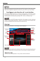
Front Panel Connectors: JFP1, JFP2
These connectors are for electrcal connecton to the front panel swtches and LEDs.
The JFP1 s complant wth Intel
®
Front Panel I/O Connectvty Desgn Gude.
1
.Ground
3.Suspend
LE
D
5.Power
LE
D
7.No Pi
n
8.
+
6.
-
4.
+
2.
-
Buzzer
S
peaker
1.+
3.
-
10.No
Pi
n
5.
-
Reset
S
witch
HDD
LE
D
P
ower
S
witch
P
ower
LE
D
7.
+
9.Reserve
d
8.
-
6.
+
4.
-
2.
+
JFP1
JFP2
DLED3 Connector: JDLED3 (optonal)
Ths s reserved for connectng the MSI future control card.
10.N
o
Pi
n
14.Contr
o
l p
in
8.Contr
o
l p
in
11.Contr
o
l p
in
12.Contr
o
l p
in
6
.Ground
4.Control
pi
n
2.Control
p
in
1.5VSB
3.Contr
o
l p
in
5.Contr
o
l p
in
7.Contr
o
l p
in
9
.Ground
13.Ground