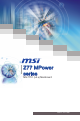
Z77 MPower series MS-7751 (v4.
Preface Copyright Notice The material in this document is the intellectual property of MICRO-STAR INTERNATIONAL. We take every care in the preparation of this document, but no guarantee is given as to the correctness of its contents. Our products are under continual improvement and we reserve the right to make changes without notice. Trademarks All trademarks in this manual are properties of their respective owners. ■ MSI® is registered trademark of Micro-Star Int’l Co.,Ltd.
MS-7751 Technical Support If a problem arises with your system and no solution can be obtained from the user’s manual, please contact your place of purchase or local distributor. Alternatively, please try the following help resources for further guidance. http://www.msi.com/service/download Contact our technical staff at: http://support.msi.com Safety Instructions ■ ■ ■ ■ ■ Always read the safety instructions carefully. Keep this User’s Manual for future reference.
Preface FCC-B Radio Frequency Interference Statement This equipment has been tested and found to comply with the limits for a Class B digital device, pursuant to Part 15 of the FCC Rules. These limits are designed to provide reasonable protection against harmful interference in a residential installation. This equipment generates, uses and can radiate radio frequency energy and, if not installed and used in accordance with the instructions, may cause harmful interference to radio communications.
MS-7751 Radiation Exposure Statement This equipment complies with FCC radiation exposure limits set forth for an uncontrolled environment. This equipment and its antenna should be installed and operated with minimum distance 20 cm between the radiator and your body. This equipment and its antenna must not be co-located or operating in conjunction with any other antenna or transmitter.
Preface Battery Information European Union: Batteries, battery packs, and accumulators should not be disposed of as unsorted household waste. Please use the public collection system to return, recycle, or treat them in compliance with the local regulations. Taiwan: For better environmental protection, waste batteries should be collected separately for recycling or special disposal.
MS-7751 WEEE (Waste Electrical and Electronic Equipment) Statement ENGLISH To protect the global environment and as an environmentalist, MSI must remind you that... DEUTSCH Hinweis von MSI zur Erhaltung und Schutz unserer Umwelt Gemäß der Richtlinie 2002/96/EG über Elektro- und Elektronik-Altgeräte dürfen Elektro- und Elektronik-Altgeräte nicht mehr als kommunale Abfälle entsorgt werden.
Preface ESPAÑOL MSI como empresa comprometida con la protección del medio ambiente, recomienda: Bajo la directiva 2002/96/EC de la Unión Europea en materia de desechos y/o equipos electrónicos, con fecha de rigor desde el 13 de agosto de 2005, los productos clasificados como “eléctricos y equipos electrónicos” no pueden ser depositados en los contenedores habituales de su municipio, los fabricantes de equipos electrónicos, están obligados a hacerse cargo de dichos productos al termino de su período de vida
MS-7751 TÜRKÇE Çevreci özelliğiyle bilinen MSI dünyada çevreyi korumak için hatırlatır: ČESKY Záleží nám na ochraně životního prostředí - společnost MSI upozorňuje... Podle směrnice Evropské unie (“EU”) o likvidaci elektrických a elektronických výrobků 2002/96/EC platné od 13.
Preface ▍ Contents Copyright Notice �������������������������������������������������������������������������������������������� ii Trademarks ���������������������������������������������������������������������������������������������������� ii Revision History �������������������������������������������������������������������������������������������� ii Technical Support �����������������������������������������������������������������������������������������iii Safety Instructions ��������������������
MS-7751 Chapter 2 BIOS Setup ���������������������������������������������������������������������������������2-1 Entering ���������������������������������������������������������������������������������������������������������������� 2-2 Overview �������������������������������������������������������������������������������������������������������������� 2-2 Boot device priority bar ���������������������������������������������������������������������������������������� 2-3 Operation �������������������
Chapter 1 Getting Started Thank you for choosing the Z77 MPower Series (MS7751 v4.X) ATX mainboard. The Series mainboards are based on Intel® Z77 chipset for optimal system efficiency. Designed to fit the advanced Intel® LGA1155 processor, the Z77 MPower Series mainboards deliver a high performance and professional desktop platform solution.
Getting Started Packing Contents Mainboard Drivers & Utilities Disc User Guide Backplate SATA Cable Optional Accessories USB 2.0 Bracket USB 3.0 Bracket eSATA Power Cable eSATA Bracket M-Connector USB3 to USB2 Connector SATA Power Cable CrossFire Cable SLI Cable MSI MultiConnect Panel Wi-Fi Antenna * These pictures are for reference only and may vary without notice. * The packing contents may vary according to the model you purchased.
MS-7751 Assembly Precautions Important A screwdriver (not included) may be required for computer assembly. 1-3 Chapter 1 ■ The components included in this package are prone to damage from electrostatic discharge (ESD). Please adhere to the following instructions to ensure successful computer assembly. ■ Always turn off the power supply and unplug the power cord from the power outlet before installing or removing any computer component. ■ Ensure that all components are securely connected.
Getting Started Mainboard Specifications Processor Support ■ 3rd Generation Intel® Core™ i7 / Core™ i5 / Core™ i3 / Pentium® / Celeron® processors for LGA 1155 socket Chipset ■ Intel® Z77 chipset Memory Support ■ 4x DDR3 DIMMs support for DDR3-1066/1333/1600/1866*/2000*/2133*(OC), 2200*/ 2400*/2600*/2667*/2800*/3000*(OC, 22nm CPU required) MHz up to 32GB max ■ Supports Dual-Channel mode Network ■ Supports LAN 10/100/1000 Fast Ethernet by Realtek® 8111E ■ Supports Wi-Fi 802.
MS-7751 Chapter 1 - 1x DisplayPort*, supporting a maximum resolution of 2560x1600 - * This platform supports dual-display function (HDMI+DisplayPort). ■ On-Board - 3x USB 2.0 connectors - 1x USB 3.
Getting Started Connectors Quick Guide DIMM1 DIMM2 DIMM3 DIMM4 SYSFAN2 JPWR2 CPU CPUFAN JTURBO1 OC1 RESET1 POWER1 SYSFAN1 Back Panel JPWR1 FV1 JPWR3 PCI_E1 Debug LED Panel PCI_E2 JUSB4 PCI_E3 SATA1_2 PCI_E4 JBAT1 SATA3_4 PCI_E5 SATA5_6 PCI_E6 SW1 PCI_E7 MULTI BIOS SWITCH JAUD1 JFP1 SYSFAN3 SYSFAN4 JFP2 JDLED3 JTPM1 1-6 JCI1 JUSB1 JUSB2 JUSB3
MS-7751 Connectors Reference Guide Port Name Port Type Page 1-8 CPU LGA1155 CPU Socket 1-10 CPUFAN,SYSFAN1~4 Fan Power Connectors 1-25 Debug LED Panel 1-37 DIMM1~4 DDR3 Memory Slots 1-16 FV1 Voltage Checkpoints Connector 1-31 JAUD1 Front Panel Audio Connector 1-26 JBAT1 Clear CMOS Jumper 1-34 JCI1 Chassis Intrusion Connector 1-28 JDLED3 Voice Genie Connector 1-29 JFP1, JFP2 Front Panel Connectors 1-26 JPWR1 ATX 24-pin Power Connector 1-15 JPWR2 ATX 8-pin Power Connecto
Getting Started Back Panel Quick Guide Wi-Fi Antenna Mouse/Keyboard Bluetooth Module Wi-Fi Module LAN Optical S/PDIF-Out Line-In HDMI Port Line-Out CS-Out Mic USB 2.0 Port USB 3.0 Port RS-Out SS-Out DisplayPort Clear CMOS Button ▶ Mouse/Keyboard A combination PS/2® mouse/keyboard DIN connector for a PS/2® mouse/keyboard. ▶ Clear CMOS Button There is CMOS RAM present on board that is powered by an external battery to store system configuration data.
MS-7751 ▶ LAN The standard RJ-45 LAN jack is for connecting to a Local Area Network (LAN). Yellow Green/ Orange Color LED State Condition Left Yellow Off LAN link is not established. On(Steady) LAN link is established. On(flashing) The computer is communicating with another computer on the network.
Getting Started CPU (Central Processing Unit) Introduction to the LGA 1155 CPU The surface of the LGA 1155 CPU has two alignment keys and a yellow triangle to assist in correctly lining up the CPU for mainboard placement. The yellow triangle is the Pin 1 indicator. Alignment Key Alignment Key Yellow triangle is the Pin 1 indicator Important Overheating Overheating can seriously damage the CPU and mainboard. Always make sure the cooling fans work properly to protect the CPU from overheating.
MS-7751 CPU & Cooler Installation When installing a CPU, always remember to install a CPU cooler. A CPU cooler is necessary to prevent overheating and maintain system stability. Follow the steps below to ensure correct CPU and CPU cooler installation. Wrong installation can damage both the CPU and the mainboard. 2. The loading plate should automatically lift up as the loading lever is pushed to the fully open position. Do not touch any of the CPU socket pins. 3. Line up the CPU to fit the CPU socket.
Getting Started 5. Inspect the CPU to check if it is properly seated in the socket. Press the loading lever down and lock it under the retention tab. 6. Evenly spread a thin layer of thermal paste (or thermal tape) on the top of the CPU. This will help in heat dissipation and prevent CPU overheating. 7. Locate the CPU fan connector on the mainboard. 8. Place the heatsink on the mainboard with the fan’s wires facing towards the fan connector and the hooks matching the holes on the mainboard.
MS-7751 9. Push down on the heatsink until the four clips get wedged into the holes on the mainboard. Press the four hooks down to fasten the cooler. As each hook locks into position a click should be heard. 10. Inspect the mainboard to ensure that the clip-ends have been properly locked in place. Chapter 1 Mainboard Hook 11. Finally, attach the CPU fan cable to the CPU fan connector on the mainboard. Important • Do not touch the CPU socket pins.
Getting Started Mounting Screw Holes When installing the mainboard, first install the necessary mounting stands required for an mainboard on the mounting plate in your computer case. If there is an I/O back plate that came with the computer case, please replace it with the I/O backplate that came with the mainboard package. The I/O backplate should snap easily into the computer case without the need for any screws.
MS-7751 Power Supply JPWR1: ATX 24-pin Power Connector d n u ro V .G 5 V 4 2 3.+ +5 V d 2 2. +5 s un d 2 1. e o n d 2 0.R Gr rou un # 2 9. G ro ON d - n 1 8. 1 7.G PS ou 1 6. Gr 2V V 1 . 1 .3 5 1 4.- +3 1 3. 1 V .3 3 V .+ 2 V 2 1 2 1 1.+ +1 B OK 1 0. VS R nd 1 .5 W u 9 .P ro nd 8 .G 5V u d 7 .+ ro 6 .G 5V un 5 .+ ro 3V 4 G . V . 3 .+3 3.3 2 .+ 1 JPWR2: ATX 8-pin Power Connector This connector provides 12V power to the CPU. d n u d ro un nd .G ro u d 4 G ro un . 3 .G ro 2 .G 1 V 2 1 V .+ 2 V 8 .
Getting Started Memory These DIMM slots are used for installing memory modules. For more information on compatible components, please visit http://www.msi.com/service/test-report DDR3 240-pin, 1.5V 48x2=96 pin 72x2=144 pin Dual-Channel mode Population Rule In Dual-Channel mode, the memory modules can transmit and receive data with two data bus channels simultaneously. Enabling Dual-Channel mode can enhance system performance.
MS-7751 Installing Memory Modules 1. Unlock the DIMM slot by pushing the mounting clips to the side. Vertically insert the memory module into the DIMM slot. The memory module has an off-center notch on the bottom that will only allow it to fit one way into the DIMM slot. 3. Manually check if the memory module has been locked in place by the DIMM slot’s side clips. Notch Volt 1-17 Chapter 1 2. Push the memory module deep into the DIMM slot.
Getting Started Expansion Slots This mainboard contains numerous ports for expansion cards, such as discrete graphics or audio cards. PCIe (Peripheral Component Interconnect Express) Slot The PCIe slot supports the PCIe interface expansion card. PCIe 3.0 x16 Slot PCIe 2.0 x1 Slot Important When adding or removing expansion cards, always turn off the power supply and unplug the power supply power cable from the power outlet.
MS-7751 Video/ Graphics Cards If available, this mainboard takes advantage of the CPU’s integrate graphics processor, but discrete video cards can be installed by way of the mainboard’s expansion slots. Adding on one or more discrete video cards will significantly boost the system’s graphics performance. For best compatibility, MSI graphics cards are recommended. 1. Determine what type of expansion slot(s) the video card will use. Locate the expansion slot(s) on the mainboard.
Getting Started AMD CrossFire™ (Multi-GPU) Technology AMD CrossFire™ is a multi-GPU performance gaming platform. By linking together two or more discrete GPUs, CrossFire™ can significant improve system graphics performance. It allows the ability to scale a system’s graphics power as needed, making it the most scalable gaming platform. This mainboard will automatically detect CrossFire™ technology and make changes in the BIOS as needed.
MS-7751 3. Boot up the computer and install the drivers and software included in your video card package. For more information, please refer to the manual that came with your video card. 4. After all of the hardware and software has been properly installed, reboot the system. After entering the operating system (OS), right click on the desktop and choose the “Catalyst Control Center”. Chapter 1 5. The CrossFire™ setting must be enabled to allow CrossFire™ mode to operate.
Getting Started NVIDIA® SLI Technology NVIDIA’s SLI (Scalable Link Interface) technology allows two or more GPUs to run in tandem within a system to achieve significant graphics performance gains. To utilize this technology, the GPU cards must be connected by an SLI Video Link. If you intend to use SLI mode, please follow the instructions below to properly set up SLI mode. The instructions below are meant for a two video card SLI configuration. 1.
MS-7751 4. After all of the hardware and software has been properly installed, reboot the system. After entering the operating system (OS), right click on the desktop and choose the “NVIDIA Control Panel”. Chapter 1 5. Enter the NVIDIA Control Panel. Choose the “Maximize 3D Performance” setting to enable SLI mode. The configuration screen is shown below. Depending on your operating system, the screen may look different.
Getting Started Internal Connectors SATA1~6: SATA Connector This connector is a high-speed SATA interface port. Each connector can connect to one SATA device. SATA devices include disk drives (HDD), solid state drives (SSD), and optical drives (CD/ DVD/ Blu-Ray). * The MB layout in this figure is for reference only. SATA6 SATA5 SATA4 SATA3 SATA2 SATA1 SATA1~2 (6Gb/s, by Intel® Z77) SATA3~6 (3Gb/s, by Intel® Z77) Important • Many SATA devices also need a power cable from the power supply.
MS-7751 CPUFAN,SYSFAN1~4: Fan Power Connectors CPUFAN d n u ro 2V or l .G 1 s o 1 .+ en tr 2 .S on 3 .C 4 d n u ro 2V or .G 1 s e 1 + en Us . 2 .S o 3 .N 4 SYSFAN1/ SYSFAN2/ SYSFAN3/ SYSFAN4 Important • Please refer to your processor’s official website or consult your vendor to find recommended CPU cooling fans. • The CPUFAN, SYSFAN1~4 connectors support Smart Fan Control with liner mode.
Getting Started JFP1, JFP2: Front Panel Connectors 2 .+ 8 . 6 .+ 4 . These connectors connect to the front panel switches and LEDs. The JFP1 connector is compliant with the Intel® Front Panel I/O Connectivity Design Guide. When installing the front panel connectors, please use the enclosed mConnectors to simplify installation. Plug all the wires from the computer case into the mConnectors and then plug the mConnectors into the mainboard. r ake Spe zer Buz D D in E LE P rL d o e n .N w e d 7 .Po sp n 5 .
MS-7751 JUSB1~3: USB 2.0 Expansion Connectors This connector is designed for connecting high-speed USB peripherals such as USB HDDs, digital cameras, MP3 players, printers, modems, and many others. 115V Chapter 1 d C un + .N o 1 0 r B 11 .G 8 US B . S 6 .U C 4 VC . 2 in P nd o u + .N ro 0 9 .G SB 07 U B . S 5 .U CC 3 .V 1 * The MB layout in this figure is for reference only. USB 2.
Getting Started JUSB4: USB 3.0 Expansion Connector The USB 3.0 port is backwards compatible with USB 2.0 devices. It supports data transfer rates up to 5Gbits/s (SuperSpeed). 115V N D _ DP in N P r X _ D o e _R X _ P C D .N w 3 R _ _ 0 o B _ 2 .P S B3 nd X _C T 9 1 8.U S ou _ X 1 7.U Gr B3 _T 1 6. S B3 nd 1 .U S u .0 + o 5 1 .U r B2 .0 4 1 3.G S B2 1 2.U S 1 1.U 1 N D _ DP N r X _ D e R X _ P w _ o B3 _R _C _D .P S 3 d X C 1 .U B n T _ 2 .US rou 3_ TX 3 .G SB 3_ d 4 .U B n 0 5 US rou 2. 0 + . 6 .G SB 2.
MS-7751 JTPM1: TPM Module connector This connector connects to a TPM (Trusted Platform Module). Please refer to the TPM security platform manual for more details and usages. TPM module is optional Chapter 1 115V 3 in p 2 ta in a p 1 d ta pin 0 n e s & da ta pi m s & da ta a ra re s F d s & d C ad dre ss & P re s .L C d d s 3 P a d re 1 1.L C a dd et 1 .LP C a es k 9 .LP C R loc 7 .LP C C 5 .LP C 3 .LP 1 d n u d r ro un n r e .G ro Pi we Q r ow 4 1 2.G o Po IR we y p l 1 .N a o b V i 0 1 .5 er P nd 8 .
Getting Started JTURBO1: MultiConnect Panel Connector (optional) This connector is used to connect an optional front panel for controling the OC Genie and some additional functions. Please refer to its user guide for more details and usages. in lP o tr n O o RB .C 2 .TU 1 in P O o RB .N 4 .
MS-7751 FV1: Voltage Checkpoints Connector These voltage checkpoint are used to measure the current system voltages. A multimeter (not included) will be required to check voltages. To check the voltage, please use the included voltage checkpoint cables included in the mainboard package. Attach the positive lead of the multimeter to the voltage checkpoint cable and the negative lead to the ground connector.
Getting Started Buttons The mainboard has numerous on-board buttons to control various functions. This section will explain how to change your mainboard’s functions through the use of these on-board buttons. OC1: OC Genie Button This button is used to automatically overclock the system. Press this button once while the system is off to enable OC Genie. The button will lock remain depressed until it is pushed again to disable OC Genie.
MS-7751 POWER1: Power Button This button is use to turn-on and turn-off the system. Press the button once to turn-on or turn-off the system. Chapter 1 RESET1: Reset Button This reset button is used to reset the system. Press the button to reset the system. SW1: GO2BIOS Button This button is used to force the system to enter the BIOS while booting. Press this button in any state (OS, BIOS, power off ...), the system will enter BIOS at next booting.
Getting Started Jumpers JBAT1: Clear CMOS Jumper There is CMOS RAM onboard that is external powered from a battery located on the mainboard to save system configuration data. With the CMOS RAM, the system can automatically boot into the operating system (OS) every time it is turned on. If you want to clear the system configuration, set the jumpers to clear the CMOS RAM. 1 Keep Data 1 Clear Data Important You can clear the CMOS RAM by shorting this jumper while the system is off.
MS-7751 Switch MULTI BIOS SWITCH: Multi-BIOS Switch A B BIOS recovery using the M-flash utility: 1. Ensure that the system is switched off. 2. Boot up the system with the operational BIOS ROM by switching the Multi-BIOS switch. 3. Enter the BIOS setup → UTILITIES → M-Flash → Save BIOS to storage and then save the file to a bootable USB pen drive (root folder). 4. Switch back to the BIOS ROM that needs to be recovered. 5.
Getting Started LED Status Indicators DrMOS_ALARM LED CPU_PHASE LEDs Debug LED Panel BIOS LEDs HDD LED CPU_PHASE LEDs These LEDs will change according to CPU loading. The higher the power phase number, the more reliable the power flow to the processor. DrMOS_ALARM LED This LED will light red when DrMOS overheat. BIOS LEDs These LEDs are used to distinguish BIOS A or B is in operation. When the left LED lights blue, the BIOS A is in operation.
MS-7751 Debug LED Panel Please refer to the table below to get more information about the Debug LED message.
Getting Started Drivers and Utilities After you install the operating system you will need to install drivers to maximize the performance of the new computer you just built. MSI mainbaord comes with a Driver Disc. Drivers allow the computer to utilize your mainboard more efficiently and take advantage of any special features we provide. You can protect your computer from viruses by installing the bundled security program. The bundle also includes a variety of powerful and creative utilities.
Chapter 2 BIOS Setup CLICK BIOS II is a revolutionary UEFI interface that allows you to setup and configure your system for optimum use. Using your mouse and keyboard, users can change BIOS settings, monitor CPU temperature, select the boot device priority and view system information such as the CPU name, DRAM capacity, the OS version and the BIOS version. Users can import and export parameter data for backup or for sharing with friends.
BIOS Setup Entering Power on the computer and the system will start the Power On Self Test (POST) process. When the message below appears on the screen, please key to enter CLICK BIOS II: Press DEL key to enter Setup Menu, F11 to enter Boot Menu If the message disappears before you respond and you still need to enter CLICK BIOS II, restart the system by turning the computer OFF then back ON or pressing the RESET button.
MS-7751 Boot device priority bar This bar shows the priority of the boot devices. The lighted icons indicate that the devices are available. High priority Low priority Click and draw the icon to left or right to specify the boot priority.
BIOS Setup Operation CLICK BIOS II allows you to control BIOS settings with the mouse and the keyboard. The following table lists and describes the hot keys and the mouse operations.
MS-7751 SETTINGS Chapter 2 System Status ▶ System Date This allows you to set the system date that you want (usually the current date). The format is . day Day of the week, from Sun to Sat, determined by BIOS. Read-only. month The month from Jan. through Dec. date The date from 1 to 31 can be keyed by numeric function keys. year The year can be adjusted by users. ▶ System Time This allows you to set the system time that you want (usually the current time).
BIOS Setup ▶ PCIE GEN3 This item is used to enable (Auto)/ disable (Disabled) the PCIe generation 3 support. ▶ PCI Latency Timer Controls how long each PCI device can hold the bus before another takes over. When set to higher values, every PCI device can conduct transactions for a longer time and thus improve the effective PCI bandwidth. ▶ ACPI Settings Press to enter the sub-menu. ▶ ACPI Standby State Specifies the power saving mode for ACPI function [S1] Sleep Mode. Hardware remains on.
MS-7751 Important • Windows XP is not natively supported to be installed in the storage device with AHCI mode. If you still prefer to install Windows XP as the operating system, please refer to Appendix Install Windows XP Notes. • You cannot switch between AHCI and IDE if you already have your operating system installed. ▶ Port 1~6 Hot Plug These items are used to enable/ disable the SATA ports hot plug support. ▶ HD Audio Controller This item allows you to enable/ disable the HD audio controller.
BIOS Setup ▶ USB Configuration Press to enter the sub-menu. ▶ USB Controller This item allows you to enable/ disable the integrated USB 2.0 controller. ▶ Legacy USB Support Enable or disable support for USB keyboards, mice and floppy drives. You will be able to use these devices with operating systems that do not support USB. ▶ Onboard USB 3.0 Controller This item allows you to enable/ disable the USB 3.0 controller. ▶ Hardware Monitor Press to enter the sub-menu.
MS-7751 ▶ Wake Up Event Setup Press to enter the sub-menu. ▶ Wake Up Event By Setting to [BIOS] activates the following fields, and use the following fields to set the wake up events. Setting to [OS], the wake up events will be defined by OS. ▶ Resume By RTC Alarm The field is used to enable or disable the feature of booting up the system on a scheduled time/date.
BIOS Setup ▶ Save Changes Use this item to save changes. ▶ Discard Changes Use this item to abandon all changes. ▶ Restore Defaults Use this item to load the optimized default values set by the BIOS vendor. == Boot Override == The installed storage devices will appear on this menu, you can select one of them be a boot device. ▶ Built-in EFI Shell Use this item to enter the EFI Shell.
MS-7751 OC Chapter 2 Important • Overclocking your PC manually is only recommended for advanced users. • Overclocking is not guaranteed, and if done improperly, can void your warranty or severely damage your hardware. • If you are unfamiliar with overclocking, we advise you to use OC Genie for easy overclocking. ▶ Current CPU / DRAM Frequency These items show the current clocks of CPU and Memory speed. Read-only. ▶ CPU Base Frequency [10KHz] Allows you to set the CPU Base clock (in 10KHz increments).
BIOS Setup ▶ EIST Enhanced Intel SpeedStep technology allows you to set the performance level of the microprocessor whether the computer is running on battery or AC power. This field only appears with installed CPUs that support this technology. ▶ Intel Turbo Boost Enables or disables Intel Turbo Boost which automatically boosts CPU performance above rated specifications (when applications requests the highest performance state of the processor).
MS-7751 ▶ My OC Genie Long duration power limit This field allows you to customize Long duration power limit for OC Genie function. ▶ My OC Genie Long duration maintained This field allows you to customize Long duration maintained for OC Genie function. ▶ My OC Genie Short duration power limit This field allows you to customize Short duration power imit for OC Genie function.
BIOS Setup ▶ tRP Controls number of cycles for RAS (row address strobe) to be allowed to pre-charge. If insufficient time is allowed for RAS to accumulate before DRAM refresh, the DRAM may fail to retain data. This item applies only when synchronous DRAM is installed in the system. ▶ tRAS Determines the time RAS (row address strobe) takes to read from and write to memory cell. ▶ tRFC This setting determines the time RFC takes to read from and write to a memory cell.
MS-7751 Spectrum for EMI reduction. • The greater the Spread Spectrum value is, the greater the EMI is reduced, and the system will become less stable. For the most suitable Spread Spectrum value, please consult your local EMI regulation. • Remember to disable Spread Spectrum if you are overclocking because even a slight jitter can introduce a temporary boost in clock speed which may just cause your overclocked processor to lock up. ▶ Hybrid Digital Power Press to enter the sub-menu.
BIOS Setup ▶ Save Overclocking Profile 1/ 2/ 3/ 4/ 5/ 6 Save the current overclocking settings to ROM for selected profile. ▶ Load/ Clear Overclocking Profile 1/ 2/ 3/ 4/ 5/ 6 Load/ Clear the stored profile settings from ROM. ▶ OC Profile Save to USB Save the current overclocking settings to USB drive. ▶ OC Profile Load from USB Load the stored settings from USB drive. ▶ CPU Specifications Press to enter the sub-menu. This sub-menu highlights all the key features of your CPU.
MS-7751 ▶ Intel Virtualization Tech Enhances virtualization and allows the system to act as multiple virtual systems. See Intel’s official website for more information. ▶ Intel VT-D Tech This item is used to enable/disable the Intel VT-D technology. For further information please refer to Intel’s official website. ▶ Power Technology This item allows you to select the Intel Dynamic Power technology mode.
BIOS Setup ECO Important Once you click the “ECO” button in the pre-set area, some items in ECO menu will be fixed and un-adjustable. ▶ EuP 2013 Energy Using Products Lot 6 2013 (EUP) reduces power consumption when system is off or in standby mode. Note: When enabled, the system will not support RTC wake up event functions. ▶ CPU Phase Control These items allow you to enable (Auto)/ disable (disabled) the CPU power phase switch feature to reach the best power saving.
MS-7751 BROWSER Please install the MSI "Winki" application first in the Windows operating system with the MSI Driver Disc before using the browser. Then you can click the BROWSER to access the Internet, e-mail and instant messaging. Chapter 2 Installing Winki To install Winki, follow the steps below: 1. Power on your computer and enter Windows operating system. 2. Insert MSI Driver Disc into the optical drive. The setup screen will automatically appear. 3. Click Driver tab. 4. Click OTHERS button. 5.
BIOS Setup UTILITIES ▶ HDD Backup Hard disk storage backups and restoring is one of the most common and important tasks. Use this utility to create an image of your HDD partitions and re-load them when necessary. Important The HDD Backup can’t back up (/restore) image to (/from) a partition where itself was installed, so it’s strongly recommended to divide HDD into 2 partitions at least (1st for OS; 2nd for data). For HDD with single partition only, the requirements for HDD Backup are: 1.
MS-7751 ▶ M-Flash ▶ BIOS Boot Function This allows you to enable/ disable the system to boot from the BIOS file inside USB drive (FAT/ 32 format only). ▶ Select one file to Boot When the BIOS Boot function as sets to [Enabled], this item is selectable. This item allows to select particular BIOS file from the USB/ Storage (FAT/ 32 format only) drive. And the system will boot from selected BIOS file. ▶ Update BIOS Press to enter the sub-menu.
BIOS Setup Updating the BIOS with Live Update This section tells you how to update the BIOS by using the Live Update utility before entering Operating System. Live Update will update the BIOS automatically when connecting to the Internet. To update the BIOS with the Live Update utility: 1. Click Live Update button installed). on the BIOS UTILITIES menu. (The Winki must be 2. Setup the connection by click the setting button 3. Click the next button if necessary. . 4.
MS-7751 SECURITY Chapter 2 ▶ Administrator Password Set the administrative password that will be required to enter the BIOS. ▶ User Password Set the user password that will be required to enter the operating system. Important When selecting the Administrative / User Password items, a password box will appear on the screen. Type the password then press . The password typed now will replace any previous set password from CMOS memory. You will be prompted to confirm the password.
BIOS Setup ▶ Chassis Intrusion Configuration Press to enter the sub-menu. ▶ Chassis Intrusion Enables or disables the feature of recording the chassis intrusion status and issuing a warning message if opened. To clear the warning logs, set the field to [Reset]. The setting of the field will return to [Enabled] later.
Appendix A Realtek Audio The Realtek audio provides 10-channel DAC that simultaneously supports 7.1 sound playback and 2 channels of independent stereo sound output (multiple streaming) through the Front-Out-Left and Front-Out-Right channels.
Realtek Audio Software Configuration After installing the audio driver (see Chapter 1 - Driver and Utilities), the “Realtek HD Audio Manager” icon will appear at the notification area (lower right of the screen). You may double click the icon and the GUI will pop up accordingly. double click the icon It is also available to enable the audio driver by clicking the Realtek HD Audio Manager from the Control Panel.
MS-7751 ■ Device Selection Here you can select a audio output source to change the related options. The “check” sign (in orange) indicates the devices as default. ■ Volume Adjustment You can control the volume or balance the right/left side of the speakers that you plugged in front or rear panel by adjust the bar. ■ Application Enhancement The array of options will provide you a complete guidance of anticipated sound effect for both output and input device.
Realtek Audio Hardware Default Setting The following diagrams are audio back panel default setting.
MS-7751 ■ Backpanel audio jacks to 6-channel speakers diagram Fro nt Cen ter &S ubw Rea oof r er Appendix A ■ Backpanel audio jacks to 8-channel speakers diagram Fro nt Cen ter S id &S eS ubw urro Rea oof r er und A-5
Appendix B Intel RAID This appendix will assist users in configuring and enabling RAID functionality and accelerating system on platforms
Intel RAID Introduction The mainboard comes with the Intel RAID controller that allows you to configure SATA hard drives as RAID sets. SATA hard drives deliver blistering transfer speeds up to 6 Gb/s. Serial ATA uses long, thin cables, making it easier to connect your drive and improving the airflow inside your PC. The most outstanding features are: 1. Supports 3 Gb/s or 6 Gb/s transfers with CRC error checking. 2. Supports Hot-plug-n-play feature. 3.
MS-7751 Using Intel Rapid Storage Technology Option ROM The Intel Rapid Storage Technology Option ROM should be integrated with the system BIOS on all mainboards with a supported Intel chipset. The Intel Rapid Storage Technology Option ROM is the Intel RAID implementation and provides BIOS and DOS disk services. Please use + keys to enter the “Intel® RAID for Serial ATA” status screen, which should appear early in system boot-up, during the POST (PowerOn Self Test).
Intel RAID After pressing the and keys simultaneously, the following window will appear: [ [ MAIN MAIN MENU ] ] 1. 2. 3. 4. Recovery Volume Options Create RAID Volume 5. Acceleration Options Delete RAID Volume 6. Exit Reset Disks to Non-RAID [ DISK / VOLUME INFORMATION ] RAID Volumes : None defined. Physical Devices : Port Device Model 1 XXXX-XXXXXXXX 2 XXXX-XXXXXXXX [ ↑↓] - Select Serial # XXXXXXXXXXXXXX XXXXXXXXXXXXXX [ESC] - Exit Size Type/Status (Vol ID) XXX.XGB Non-RAID Disk XXX.
MS-7751 3. In the Disk field, press key and use key to select the disks you want to create for the RAID volume, then click key to finish selection. This field will become available according to the selected RAID level. 4. Then select the strip size for the RAID array by using the “upper arrow” or “down arrow” keys to scroll through the available values, and pressing the key to select and advance to the next field.
Intel RAID 6. Go to the Create Volume field and press , the following screen appears for you to confirm if you are sure to create the RAID volume. Press to continue. [ CREATE VOLUME MENU ] Name : RAID Level : Disks : Strip Size : Capacity : Sync : Volume0 RAID1(Mirror) Select Disks N/A XXX.X GB N/A Create Volume WARNING : ALL DATA ON SELECTED DISKS WILL BE LOST. Are you sure you want[ toHELP create] this volume? (Y / N) : Press ENTER to create the specified volume.
MS-7751 ■ Delete RAID Volume Here you can delete the RAID volume, but please be noted that all data on RAID drives will be lost. Important If your system currently boots to RAID and you delete the RAID volume in the Intel RAID Option ROM, your system will become un-bootable. Select option 2 Delete RAID Volume from the main menu screen and press key to select a RAID volume for deletion. Then press key to delete the selected RAID volume. The following screen appears.
Intel RAID ■ Reset Disks to Non-RAID Select option 3 Reset Disks to Non-RAID and press to delete the RAID volume and remove any RAID structures from the drives. The following screen appears: [ MAIN MENU ] 4. Recovery Volume Options Create RAID Volume 4. ] Recovery Volume Options Delete RAID Volume [ RESET RAID DATA 5. remove Exit its RAID structures Resetting RAID disk will VOLUME INFORMATION and revert [ it DISK to a / non-RAID disk. ] 1. 2.
MS-7751 ■ Recovery Volume Options Select option 4 Recovery Volume Options and press to change recovery volume mode. The following screen appears: [ RECOVERY VOLUME OPTIONS ] 1. 2. Enable Only Recovery Disk Enable Only Master Disk [ HELP ] Enable Only Recovery Disk - enables recovery disk if available and disables master disk. Enable Only Master Disk - enables master disk if available and disables recovery disk. Actions will result in change from Continuous Update mode to On-Request.
Intel RAID Installing Driver ■ New Windows 7/ Windows XP Installation The following details the installation of the drivers while installing operating system. 1. When you start installing Windows XP, you may encounter a message stating, “Setup could not determine the type of one or more mass storage devices installed in your system”. If this is the case, then you are already in the right place and are ready to supply the driver.
MS-7751 ■ Existing Windows Driver Installation 1. Insert the MSI DVD into the DVD-ROM drive. 2. The DVD will auto-run and the setup screen will appear. 3. Under the Driver tab, click on Intel RAID Drivers. 4. The drivers will be automatically installed. ■ Confirming Windows Driver Installation 1. From Windows, open the Control Panel from My Computer followed by the System icon. 2. Choose the Hardware tab, then click the Device Manager tab. 3.
Intel RAID Degraded RAID Array A RAID 1, RAID 5 or RAID 10 volume is reported as degraded when one of its hard drive members fails or is temporarily disconnected, and data mirroring is lost. As a result, the system can only utilize the remaining functional hard drive member. To re-establish data mirroring and restore data redundancy, refer to the procedure below that corresponds to the current situation. Missing Hard Drive Member 1. Make sure the system is powered off. 2. Reconnect the hard drive. 3.
MS-7751 5. Exit Intel RAID Option ROM, and then reboot to Windows system. 6. When prompted to rebuild the RAID volume, click ‘Yes’. 7. The Intel Rapid Storage Technology application will be launched. Right-click the new hard drive and select ‘Rebuild to this Disk’. The ‘Rebuild Wizard’ will be launched which will guide you through the process of rebuilding to the new hard drive.
Intel RAID System Acceleration (optional) Intel® Rapid Storage Technology use a SSD as a cache. Which can store frequently used data without having to use a slow virtual disk or depend on RAM. The SSD cache with the advantages of high-speed read/write and non-volatile memory to accelerate the system performance. Important Check your SSD manufacturer's website, upgrade firmware in order to support Intel® Rapid Storage Technology. Intel® Rapid Storage Technology can only work with RAID mode.
MS-7751 11. Run Intel® Rapid Storage Technology application. 12. Click "Enable acceleration" under Accelerate. Click here 13. Select the acceleration options. Important You can click “More help on this page” or "More help" of the Intel® Rapid Storage Technology application to view more information. B-15 Appendix B 14. Click OK and reboot the system. The page refreshes and reports the new acceleration configuration in the Acceleration View.
Intel RAID RST Synchronization (optional) If you are using Maximized mode as the Acceleration mode, the data on the hard disk is not always synchronized with the data in the SSD cache. In some situations, you may want to manually sync the disks for avoiding data loss. Follow these steps to sync manually. 1. Reboot system, during the Power-On Self Test (POST) press, press and keys simultaneously to enter the Intel Rapid Storage Technology Option ROM. 2.
Appendix C Install Windows XP Notes This chapter describes how to install Windows XP with IDE or AHCI mode.
Install Windows XP Notes Installing Windows XP with IDE Mode You will fail and encounter a blue screen while installing Windows XP, because it is not natively supported to be installed in the storage device with AHCI mode. If you still prefer to install Windows XP as the operating system, please change the BIOS item as below. 1. Refer to Chapter 2 to access BIOS. 2. Go to SETTINGS → Integrated Peripherals → SATA Mode. 3. Set this item to IDE mode. 4. Go to SETTINGS → Save & Exit → Save changes and reboot.
MS-7751 Installing Windows XP with AHCI Mode If you prefer to install Windows XP as the operating system with AHCI mode, please prepare AHCI drivers for Windows XP in advanced. Creating a Intel AHCI Driver Disc Please follow the instruction below to make an “Intel® AHCI Driver” for yourself. ■ Insert the MSI DVD into the DVD-ROM drive. ■ Click the “Browse CD” on the Setup screen. ■ Copy all the contents from \\Storage\Intel\PCH 7\f6flpy-x86 or f6flpy-x64 to a formatted floppy diskette.