Installation Manual Beam Series Top of Pole Mount www.mtsolar.us 844-MT-SOLAR (687-6527) 2017 V3.
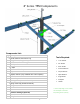
8” Series TPM Components Components List: Qty Description 2 Center I-Beams, 90 Inches Long Tools Required: 4 Wing I-Beams, Lengths Vary 1 1/8” Socket 3/4” Socket 9/16” Socket Crescent Wrench 1 Adjuster Torque Wrench 1 Adjuster Handle (only available with screw adjuster) Tape Measure 1 Back Plate Angle Finder Compass Ladder 2 3x5 Tubes, 90 Inches Long 1 4.
Thank you for choosing MT Solar Pole Mounts. It is the installer’s responsibility to determine the foundation parameters based on local site conditions, such as wind speed, snow load, soil type, exposure category, etc. Installations also must comply with local building regulations and permitting requirements. We recommend consulting a licensed engineer to determine appropriate foundation dimensions and pipe size and thickness.
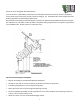
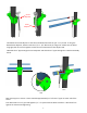
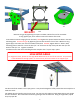
Installation Guide 101 102 104 A 103 101: With the 8" Sch 40 or Sch 80 steel pipe installed in the ground, place the lifting insert into the top of the pipe until it sits flush. 104 B 102: Place the lifting bracket into the lifting insert with the eye facing south. 103: Hang a 1 ton or greater chain fall hoist from the lifting eye. 104: Hang the U-Bracket Assembly on the Chain Hoist. NEW! Optional Safety Chain Tie-Off. Connect the pole cap to the lifting bracket with a 3/8” chain.
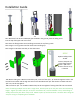
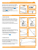
Screw Adjuster Plate Adjuster 107 B 107 A 108 107: Attach the Screw Adjuster to the tab on the Back Plate with the 1/2” x 1 1/2” Bolt. If using the Manual Plate Adjuster, attach it with the 1/2” x 1 1/2” Bolt and 1/2” flange nut. Make sure the bolt is snug tight, but do not over-tighten to allow for some movement of the adjuster tab. 108: Slide the 2” pipe through the screw adjuster and slide the 4.5" pipe through the U Bracket Assembly sleeve. 16” 16” 109 110 A 110B 109: Center pipes in sleeves.
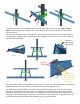
111 A 112 111 B 111: Attach one of the 3x5 rectangular tubes to the 4.5” pipe using the 3/4” x 5” bolts, large 5” square plates and 3/4” split washers. Attach to the 2” pipe using the 1/2” x 4 1/2” bolts with 1/2” flat washers and split washers. 112: Install the remaining 5"x3" rectangular tube. Snug up all 4 bolts, but leave loose enough to allow for some play when installing I-beams. Adjusting the Screw Adjuster as necessary, level the array in preparation for I-Beam installation.
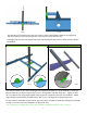
115 A 115 B 115: Standing on the North Side of the array with the Tube to Beam bolts started but not tightened, sight the beams to ensure they are parallel. If not, twist the array until they are. . Then tighten all the 3/4” bolts between the Pipe and Rectangular Tubes and the Tubes and the I-Beams to 100 ft lbs. Standard Beam Clamps Long Beam Clamps for Rails >168” 116 B 116 A 116: Plan the layout of your rails according to your module manufacturer’s recommendation.
117 118 204” Rail Connection 117: Install the Mounting Rail into the beam clamps slot as per Mounting Rail instructions. Use 3/8” x 1” stainless steel bolts and 3/8” serrated flange nuts. 118: Center rails over I-beams, keeping equal length of rail off the end of each beam. Tighten to 17 ft lbs. Install Solar Modules as per Mounting Rail and module manufacturer instructions. See last page of manual for Iron Ridge Rail and Clamp instructions.
122 121A NO GAP!! 121B *Remove the gap by tightening the square set bolts until the front of the U-Bracket is snug against pipe, then make one more full rotation of the bolt. 121A: With the mount hanging free on the hoist, FIRST tighten the square-headed set bolts in the back mounting plate. Remove the gap by tightening the set bolts until the front of the U-Bracket is snug against pipe, then make one more full rotation of the bolt. SECOND, tighten both 11” bolts in back mounting plate to 100 ft-lb.
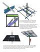
IRON RIDGE UFO CLAMP INSTALLATION GUIDE 3. SECURE LUGS Insert T-bolt in top rail slot and torque hex nut to 80 inlbs. Install a minimum 10 AWG solid copper or stranded grounding wire. Torque terminal screw to 20 in-lbs. Terminal Screw (20 in-lbs) íí Grounding Lugs are only needed on one rail per row of modules (unless frameless modules are being used, see Page 8). íí If using Enphase microinverters, Grounding Lugs may not be needed. See Page 8 for more information.
POLE CAP DETAIL A SCALE 1 : 8 Instructions: HIGH WIND ADDENDUM NAME 3/30/17 DATE A REV SHEET 1 OF 1 Note: Adjuster and Support Pole Omitted for Clarity Pole Mount Side View The bolt-through option may be required if your array meets the following criteria: - TOP-12 or larger, < 45 degree tilt, Exp C - TOP-15 or larger, < 45 degree tilt, Exp B or C *Please contact MT Solar if you need help determining whether or not this is required.
8 Module Configuration 9 Module Configuration 10-TALL Configuration 12 Module Configuration 16 Module Configuration 20 Module Configuration 10 Module Configuration 15 Module Configuration