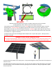
Installation Manual Beam Series Top of Pole Mount www.mtsolar.us 844-MT-SOLAR (687-6527) 2019 V3.
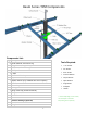
Beam Series TPM Components Components List: Qty Description 2 Center I-Beams, 90 Inches Long Tools Required: 4 Wing I-Beams, Lengths Vary 2 3x5 Tubes, 90 Inches Long 1 1/8” Socket 3/4” Socket 9/16” Socket 1 U Bracket / Pole Cap Crescent Wrench 1 Adjuster Torque Wrench 1 Adjuster Handle (only available with screw adjuster) Tape Measure 1 Back Plate ** Beam Clamps Angle Finder Compass Ladder 1 4.
Thank you for choosing MT Solar Pole Mounts. It is the installer’s responsibility to determine the foundation parameters based on local site conditions, such as wind speed, snow load, soil type, exposure category, etc. Installations also must comply with local building regulations and permitting requirements. We recommend consulting a licensed engineer to determine appropriate foundation dimensions and pipe size and thickness.
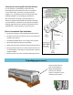
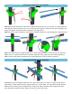
Installation Guide Safety Chain Tie-Off. Connect the pole cap to the lifting bracket with a 3/8” chain. Shorten chain as array is hoisted. 101 102 103 104 A 104 B Optional 101: With the vertical steel support pipe installed in the ground, place the lifting insert into the top of the pipe until it sits flush with the top. 102: Place the lifting bracket into the lifting insert with the eye facing south. 103: Hang a 1 ton or greater chain fall hoist from the lifting eye.
Use hardware labeled STEP 2 in the Bolt Kit Screw Adjuster Plate Adjuster 108 107 B 107 A 107: Attach the Screw Adjuster to the tab on the Back Plate with the 1/2” x 1 1/2” Bolt. If using the Manual Plate Adjuster, attach it with the 1/2” x 1 1/2” Bolt and 1/2” flange nut. Make sure the bolt is snug tight, but do not over-tighten to allow for some movement of the adjuster tab. 108: Slide the 2.5” pipe through the screw adjuster sleeve & slide the 4.5" pipe through the U Bracket sleeve.
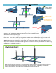
Use hardware labeled STEP 4 in the Bolt Kit Notches in I-beam flange must face up. 113 A 113 C 113 B 114 B Additional 1/2” bolts for HD Series. Standard Series will not have holes for these bolts. Alignment Set Bolts 114 A 115 113: Install center I-beams to the 3x5 tubes using the 3/4" x 2” bolts, 3/4” flat washers & 3/4” split washers. DO NOT TIGHTEN at this step. Install all I-beams with notches in the flange facing up.
116 A 116 B 116: Standing on the North Side of the array with the Tube to Beam bolts started but not tightened, sight the beams to ensure they are parallel. If not, twist the array until they are. Then tighten all the 3/4” bolts between the Pipe and Rectangular Tubes and the Tubes and the I-Beams to 100 ft lbs. Standard Beam Clamps OR 117 A Long Beam Clamps for 204” Rails 117 B 117: Plan the layout of your rails according to your module manufacturer’s recommendation.
118 119 204” Rail Connection 118: Install the Mounting Rail into the beam clamps slot as per Mounting Rail instructions. Use 3/8” x 1” stainless steel bolts and 3/8” serrated flange nuts. 119: Center rails over I-beams, keeping equal length of rail off the end of each beam. Tighten to 17 ft lbs. Install Solar Modules as per Mounting Rail and module manufacturer instructions. 121 120 120: Leave out the appropriate module(s) to allow for the 8” pipe.
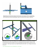
122 121A NO GAP!! 121B *Remove the gap by tightening the square set bolts until the front of the U-Bracket is snug against pipe, then make one more full rotation of the bolt. 121A: With the mount hanging free on the hoist, FIRST tighten the square-headed set bolts in the back mounting plate. Remove the gap by tightening the set bolts until the front of the U-Bracket is snug against pipe, then make one more full rotation of the bolt.
SPIN PREVENTION ADDENDUM Through-bolts are required for the following sizes: • TOP-12 or larger, 60C & 72C = 2 BOLTS • TOP-15-TALL-72C = 3 BOLTS • TOP-20-TALL-60C = 3 BOLTS NOTE: ONLY ONE SIDE SHOWN. REPEAT ON OPPOSITE SIDE FOR 2ND BOLT AND FRONT FOR 3RD BOLT POLE CAP DETAIL A SCALE 1 : 8 15/32" hole in U-Bracket Instructions: This is the final step in the installation, to be done once array is installed, hoisted into place, and the set bolts are tightened.
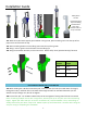
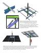
8 Module Configuration 9 Module Configuration 10-TALL Configuration 12 Module Configuration 16 Module Configuration 20 Module Configuration 10 10 Module Configuration 15 Module Configuration