Safety • Assembly • Operation • Tips & Techniques • Maintenance • Troubleshooting • Parts Lists • Warranty OPERATOR’S MANUAL 22-inch Rotary Mower — Model Series 030 IMPORTANT READ SAFETY RULES AND INSTRUCTIONS CAREFULLY BEFORE OPERATION Warning: This unit is equipped with an internal combustion engine and should not be used on or near any unimproved forest-covered, brushcovered or grass-covered land unless the engine’s exhaust system is equipped with a spark arrester meeting applicable local or state laws
This Operator’s Manual is an important part of your new lawn mower. It will help you assemble, prepare and maintain the unit for best performance. Please read and understand what it says. Table of Contents Slope Gauge........................................................ 3 Safe Operation Practices.................................... 4 Setup and Adjustment........................................ 6 Operating Your Lawn Mower............................. 12 Maintaining Your Lawn Mower........................
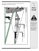
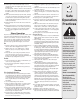
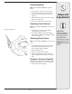
1 Use this page as a guide to determine slopes where you may not operate safely. Do not operate your lawn mower on such slopes. Slope Gauge 3IGHT AND HOLD THIS LEVEL WITH A VERTICAL TREE &O OR A FENCE POST OR A CORNER OF A BUILDING OT LD ALO NG D ESEN TED L I N E REPR LOPE TS A S WARNING Do not mow on inclines with a slope in excess of 15 degrees (a rise of approximately 2-1/2 feet every 10 feet). Operate WALK-BEHIND mowers across the face of slopes, never up and down slopes.
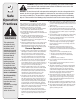
2 Safe Operation Practices WARNING This symbol points out important safety instructions which, if not followed, could endanger the personal safety and/or property of yourself and others. Read and follow all instructions in this manual before attempting to operate this machine. Failure to comply with these instructions may result in personal injury. When you see this symbol.
19. Shut the engine off and wait until the blade comes to a complete stop before removing the grass catcher or unclogging the chute. The cutting blade continues to rotate for a few seconds after the engine is shut off. Never place any part of the body in the blade area until you are sure the blade has stopped rotating. 20. Never operate mower without proper trail shield, discharge cover, grass catcher, blade control handle or other safety protective devices in place and working.
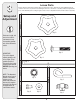
3 Loose Parts Carton contents include: wheels, handles (upper & lower), blade control, chute deflector, and a hardware pack. Be certain to remove all loose parts before discarding the carton. For convenience of assembly, identify and separate the pieces in the hardware pack according to Figure 3-1 below. A set of adjustable wrenches will be needed for assembly. GROUP 1 Setup and Adjustment GROUP 3 Qty. 2 Qty. 1 Qty. 4 Qty. 2 GROUP 6 NOTE: This Operator’s Manual covers several models.
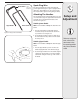
Blade Control Spark Plug Wire *blade control may be detached Disconnect spark plug wire from the spark plug and ground it against the engine. If engine is equipped with a rubber boot, attach rubber boot to a bolt on the engine. This will prevent the engine from firing during assembly. Attaching The Handles The lower handle has two flat ends with three holes each, one small and two large. The upper handle has indented ends with one hole and may have the blade control attached. See Figure 3-2.
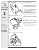
3 Setup and Adjustment Attaching Blade Control Straight End If the blade control became displaced either during shipping or during assembly, reassemble it now. If the blade control is firmly in place, you may proceed to the next step. 1. Insert the curved end of the blade control into the right hole. See Step A, Figure 3-5. Squeeze the handle in and insert the straight end of the blade control into the left hole of the upper handle. See Step B, Figure 3-5. Curved End B 2.
Attaching Wheels NOTE: Use the hardware in Group 4 to secure the wheels. 1. Place the mower on blocks up off of the ground. 2. Place the larger two wheels on the rear pivot arm axles and secure with the flanged lock nuts. See Figure 3-8. 3. Repeat with the two smaller wheels on the front pivot arm axles. See Figure 3-8. 3 Setup and Adjustment 4. Remove blocks and put the mower on ground. Attaching Chute Deflector NOTE: Use the hardware in Group 5 to secure the chute deflector.
3 Setup and Adjustment Adjustments WARNING: Always stop engine, disconnect spark plug, and ground against engine before performing adjustments. Cutting Height Each wheel has a height adjustment lever to change the cutting height of the mower. 1. Depress the lever towards the wheel. 2. Slide the lever assembly to desired position to change the cutting height. See Figure 3-11. 3. Release lever towards deck. WARNING IMPORTANT: All wheels must be positioned at the same height.
NOTES 11
4 Operating Your Lawn Mower Know Your Lawn Mower Blade Control Recoil Starter Cutting Height Adjustment Levers (one at each wheel) WARNING This blade control is a safety device. Do not bypass its operations. Use extreme care when handling gasoline. Gasoline is extremely flammable and the vapors are explosive. Never fuel the machine indoors or while the engine is hot or running. Extinguish cigarettes, cigars, pipes and other sources of ignition. Figure 4-1: The main components on the mower.
4 WARNING: The operation of any lawn mower can result in foreign objects being thrown into the eyes, which can damage your eyes severely. Always wear safety glasses while operating the mower or while performing any adjustments or repairs on it. Starting Engine WARNING: Be sure no one other than the operator is standing near the lawn mower while starting engine or operating mower. Never run engine indoors or in enclosed, poorly ventilated areas.
5 Lubrication • Lubricate pivot points on the blade control at least once a season with light oil. The blade control must operate freely in both directions. See Figure 5-1. • Lubricate the wheels at least once a season with light oil (or motor oil). If wheels are removed for any reason, lubricate surface of the axle bolt and inner surface of the wheel with light oil. See Figure 5-1.
5 Blade Care WARNING: When removing the cutting blade for sharpening or replacement, protect your hands with a pair of heavy gloves or use a heavy rag to hold the blade. Maintaining Your Lawn Mower Periodically inspect the blade adapter for cracks, especially if you strike a foreign object. Replace when necessary. 1. Disconnect spark plug wire from spark plug. Turn mower on its side making sure that the air filter and the carburetor are up. 2.
6 Engine fails to start 8. Fuel valve (if equipped) closed. 9. Engine not choked (if equipped w/choke). 8. 9. 1. Spark plug wire loose. 2. Blocked fuel line or stale fuel. Vent in gas cap plugged. Water or dirt in fuel system. Dirty air cleaner. Carburetor out of adjustment. 1. Connect and tighten spark plug wire. 2. Clean fuel line; fill tank with clean, fresh gasoline. 3. Clear vent. 4. Drain fuel tank. Refill with fresh fuel. 5. Refer to engine manual. 6. Refer to engine manual.
Safety Labels Found On Your Lawn Mower Safety Labels TO REDUCE THE RISK OF INJURY, DO NOT OPERATE UNLESS DISCHARGE COVER OR GRASS CATCHER IS IN ITS PROPER PLACE. IF DAMAGED, REPLACE IMMEDIATELY. 7/2 PLA CE MO DEL PLA TE HER ER H DEAT NJG DA Y OR ING PARTS. R U N T ROTA HE OUS I I T M AVOID SER D FEET AWAY FRO HROWN BYASSES. AN E T F ET Y G L B N A C • K E E P H AN D S A AT ND. J E C T S TH WEAR S S ARE AROU ES • REMO VE OABNY DIRECTI ON. R E P H O T L O R B L AD E IN MO W S O W N .
Model Series 030 18
Ref. No. Part No. Description 1 710-1205 Eye Bolt 2 720-0279 Wing Nut 3 747-1161A Blade Control Handle 4 749-1092A Upper Handle 5 746-0957 Blade Control Cable - 37.25 inch 746-0946 Blade Control Cable - 48.25 inch 746-1130 Blade Control Cable - 40.00 inch 6 749-04037 Lower Handle 7 725-0157 Cable Tie 8 787-01097 Deck Assembly 22-inch 9 710-0654A TT Screw 3/8-16 x 1.0 10 748-0376C Blade Adapter 11 742-0642A Standard Blade 22-inch 12 736-0452 Washer, Bell, .396 x 1.
MANUFACTURER’S LIMITED WARRANTY FOR The limited warranty set forth below is given by MTD LLC with respect to new merchandise purchased and used in the United States, its possessions and territories. “MTD” warrants this product against defects in material and workmanship for a period of two (2) years commencing on the date of original purchase and will, at its option, repair or replace, free of charge, any part found to be defective in materials or workmanship.