OPERATOR’S MANUAL 20” and 22” ROTARY MOWERS Model Series 050 thru 062 IMPORTANT: READ SAFETY RULES AND INSTRUCTIONS CAREFULLY Warning: This unit is equipped with an internal combustion engine and should not be used on or near any unimproved forestcovered, brush-covered or grass-covered land unless the engine’s exhaust system is equipped with a spark arrester meeting applicable local or state laws (if any). If a spark arrester is used, it should be maintained in effective working order by the operator.
SECTION 1: IMPORTANT SAFE OPERATION PRACTICES WARNING: THIS SYMBOL POINTS OUT IMPORTANT SAFETY INSTRUCTIONS WHICH, IF NOT FOLLOWED, COULD ENDANGER THE PERSONAL SAFETY AND/OR PROPERTY OF YOURSELF AND OTHERS. READ AND FOLLOW ALL INSTRUCTIONS IN THIS MANUAL BEFORE ATTEMPTING TO OPERATE YOUR LAWN MOWER. FAILURE TO COMPLY WITH THESE INSTRUCTIONS MAY RESULT IN PERSONAL INJURY. WHEN YOU SEE THIS SYMBOL, HEED ITS WARNING.
• Always be sure of your footing. A slip and fall can cause serious personal injury. If you feel you are losing your balance release the blade control handle immediately and the blade will stop in less than 3 seconds. • Do not engage the self-propelled mechanism on units so equipped while starting engine. • The blade control handle is a safety device. Never attempt to bypass its operation.
• After striking a foreign object, stop the engine, remove the wire from the spark plug, and thoroughly inspect the mower for any damage. Repair the damage before starting and operating the mower. • To reduce fire hazard, keep mower free of grass, leaves, or other debris build-up. Clean up oil or fuel spillage. Allow mower to cool at least 5 minutes before storing. • Before cleaning, repairing, or inspecting, make certain the blade and all moving parts have stopped.
SLOPE GAUGE SIGHT AND HOLD THIS LEVEL WITH A VERTICAL TREE A POWER POLE A CORNER OF A BUILDING OR A FENCE POST OPE A 15 ° SL 5 USE THIS PAGE AS A GUIDE TO DETERMINE SLOPES WHERE YOU MAY NOT OPERATE SAFELY. FO OTT LD O ND G NTIN PRE SE , RE ED L INE 15° WARNING Do not mow on inclines with a slope in excess of 15 degrees (a rise of approximately 2-1/2 feet every 10 feet). A riding mower could overturn and cause serious injury.
SECTION 2: CONTENTS OF HARDWARE PACK Remove this sheet from your operator’s manual and lay the hardware on the illustration for identification purposes. After Assembly, keep the Slope Gauge which is on the reverse side of this sheet for future use. (Hardware pack may contain extra items which are not used on your unit. Part numbers are shown in parentheses.) A B ATTACHING THE LOWER HANDLE ATTACHING THE UPPER HANDLE Split Washers 5/16” I.D.
SECTION 3: FINDING YOUR MODEL NUMBER This Operator’s Manual is an important part of your new walk behind. It will help you assemble, prepare and maintain your walk behind. Please read and understand what it says. Before you start to prepare your walk behind for its first use, please locate the model plate and copy the information from it in this Operator’s Manual. The information on the model plate is very important if you need help from your dealer or the MTD customer support department.
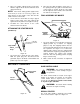
SECTION 6: ASSEMBLY INSTRUCTIONS IMPORTANT: This unit is shipped WITHOUT 7. Repeat steps 4 through 6 to attach the other side of the handle. GASOLINE or OIL. After assembly, service engine with gasoline and oil as instructed in the separate engine manual packed with your unit. 8. Tighten both hex bolts and nuts securely. ATTACHING THE UPPER HANDLE (Hardware B) NOTE: Reference to right or left hand side of the mower is observed from the operating position.
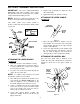
NOTE: If the control handle is disassembled from the upper handle for any reason, assemble the control handle by inserting the ends into the holes on each side of the upper handle. The hole in the control handle must be on the left side of the upper handle, and control handle must touch the upper handle when engaged (squeezed against the upper handle). 1. Remove the truss machine screw and hex lock nut from the middle of the control box using a phillips screwdriver.
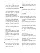
2. Place the rope guide around the starter rope, so the opening in the rope guide is toward the front of the mower as shown. Insert the rope guide into the right side of the handle, and secure with hex lock nut. See Figure 10. 3. Place one smaller cupped washer on axle bolt, with the cupped side of washer toward the deck (away from wheel).
SECTION 8: OPERATION Keep hands and feet away from the chute area on cutting deck. See Figure 1, Warning Label. 5. Pull rope with a rapid, continuous, full arm stroke. Keep a firm grip on starter handle. Return it slowly to the rope guide. The operation of any lawn mower can result in foreign objects being thrown into the eyes, which can result in severe eye damage. Always wear safety glasses or eye shields. We recommend wide vision safety mask for over spectacles or standard safety glasses.
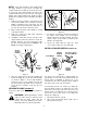
SECTION 9: ADJUSTMENTS WARNING: Do not at any time make CARBURETOR ADJUSTMENTS any adjustment to lawn mower without first stopping engine and disconnecting spark plug wire. WARNING: If any adjustments are made to the engine while the engine is running (e.g. carburetor), keep clear of all moving parts. Be careful of heated surfaces and muffler. CUTTING HEIGHT ADJUSTMENT Minor carburetor adjustment may be required to compensate for differences in fuel, temperature, altitude and load.
When sharpening the blade, follow the original angle of grind as a guide. It is extremely important that each cutting edge receives an equal amount of grinding to prevent an unbalanced blade. An unbalanced blade will cause excessive vibration when rotating at high speeds, may cause damage to the mower and could break, causing personal injury. Blade Mounting Torque The blade can be tested by balancing it on a round shaft screwdriver. Remove metal from the heavy side until it balances evenly.
SECTION 13: TROUBLE SHOOTING GUIDE Trouble Possible Cause(s) Corrective Actions Engine fails to start Blade control handle disengaged. Spark plug wire disconnected. Dirty aircleaner. Primer button not depressed. Throttle control lever not in correct starting position (if so equipped). Fuel tank empty or stale fuel. Engage blade control handle. Connect wire to spark plug. Refer to the engine manual packed with your unit. Refer to the engine manual packed with your unit.
Model 050 thru 062 15
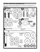
Model 050 thru 062 REF. NO. 1 2 3 4 5 6 7 8 9 13 14 18 19 20 21 22 23 24 25 26 27 28 PART NO. 734-1779 734-1780 742-0640 742-0642 742-0742 712-0324 710-1044 753-0588 738-0533 736-0105 736-0331 736-0524A 712-0798 746-0842 746-0844 746-0876 17038B 682-0086 710-0654A 17098 731-0872A 731-1029 726-0240 749-0928 710-1205 736-0119 712-0267 749710-1250 DESCRIPTION REF. NO. 29 30 Wheel Ass’y. Comp. (050 Series) Wheel Ass’y. Comp. (060 Series) 20 “ Blade 22” Blade - Std. 22” Mulching Blade Hex L-Nut 1/4-20 Thd.
NOTES 17
NOTES 18
MANUFACTURER’S LIMITED WARRANTY For ONE YEAR from the date of retail purchase within the United States of America, its possessions and territories, the manufacturer will, at its option, repair or replace, for the original purchaser, free of charge, any part or parts found to be defective in material or workmanship.