Safe Operation Practices • Set-Up • Operation • Maintenance • Service • Troubleshooting • Warranty Operator’s Manual Push Mower — Model 08M WARNING READ AND FOLLOW ALL SAFETY RULES AND INSTRUCTIONS IN THIS MANUAL BEFORE ATTEMPTING TO OPERATE THIS MACHINE. FAILURE TO COMPLY WITH THESE INSTRUCTIONS MAY RESULT IN PERSONAL INJURY. MTD LLC, P.O. BOX 361131 CLEVELAND, OHIO 44136-0019 Printed In USA Form No.
1 To The Owner Thank You Thank you for purchasing a Lawn Mower manufactured by MTD LLC. It was carefully engineered to provide excellent performance when properly operated and maintained. Please read this entire manual prior to operating the equipment. It instructs you how to safely and easily set up, operate and maintain your machine. Please be sure that you, and any other persons who will operate the machine, carefully follow the recommended safety practices at all times.
Important Safe Operation Practices 2 WARNING: This symbol points out important safety instructions which, if not followed, could endanger the personal safety and/or property of yourself and others. Read and follow all instructions in this manual before attempting to operate this machine. Failure to comply with these instructions may result in personal injury. When you see this symbol.
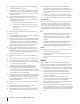
12. A missing or damaged discharge cover can cause blade contact or thrown object injuries. 13. Many injuries occur as a result of the mower being pulled over the foot during a fall caused by slipping or tripping. Do not hold on to the mower if you are falling; release the handle immediately. 14. a. Step back from mower to fully extend your arms. b. Be sure you are well balanced with sure footing. c. Pull the mower back slowly, no more than half way toward you. d. Repeat these steps as needed.
Service 3. Check the blade and engine mounting bolts at frequent intervals for proper tightness. Also, visually inspect blade for damage (e.g., bent, cracked, worn) Replace blade with the original equipment manufacture’s (O.E.M.) blade only, listed in this manual. “Use of parts which do not meet the original equipment specifications may lead to improper performance and compromise safety!” 4. Mower blades are sharp and can cut. Wrap the blade or wear gloves, and use extra caution when servicing them.
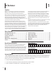
Spark Arrestor Average Useful Life Warning: This machine is equipped with an internal combustion engine and should not be used on or near any unimproved forest-covered, brush covered or grass-covered land unless the engine’s exhaust system is equipped with a spark arrester meeting applicable local or state laws (if any). If a spark arrester is used, it should be maintained in effective working order by the operator.
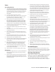
or a corner of a building... a 1 5 ° slop or a fence post ine (r ep r e s e nts dl o n g d otte l Fold a Sight and hold this level with a vertical tree... 15° Use this page as a guide to determine slopes where you may not operate safely. e) WARNING: Do not operate your lawn mower on such slopes. Do not mow on inclines with a slope in excess of 15 degrees (a rise of approximately 2-1/2 feet every 10 feet). A riding mower could overturn and cause serious injury.
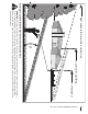
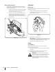
3 Assembly & Set-Up Contents of Carton • One Lawn Mower • One Lawn Mower Operator’s Manual • Assembly Handle NOTE: This lawn mower is shipped without gasoline or oil in the engine. Fill up the gasoline and oil as instructed in the accompanying engine manual BEFORE operating your mower. 1. 1. For shipping purposes, the chute deflector on your mower is held in an upright position by a retainer. Remove the retainer as follows: a. Push the chute deflector up towards the engine.
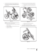
2. If satisfied with the height of the handle, tighten the star knobs at the ends of the lower handle shown in Fig. 3-3. For convenience of operation, you may adjust the handle height as follows: 3. Position the recoil starter by following the steps below: a. Hold the blade control against the upper handle. b. Slowly pull the starter rope out of the engine. See Fig. 3-4.
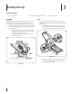
Mulching Baffle (If Equipped) Adjustments 1. Cutting Height If your mower is equipped with an optional mulching baffle, install it on the right side of the deck. Follow the sequence indicated here. a. b. Lift up and hold the side-discharge chute deflector and insert the bottom lip of the mulching baffle inside the chute opening See Fig. 3-6. Each wheel has a height adjustment lever to change the cutting height of the mower. 1. Depress the height adjustment lever towards wheel. 2.
4 Controls and Features Blade Control Choke Control Recoil Starter Cutting Height Adjustment Lever (one at each wheel) Figure 4-1 Blade Control Recoil Starter The blade control is attached to the upper handle of the mower. Depress and squeeze it against the upper handle to operate the unit. Release it to stop engine and blade. The recoil starter is attached to the right upper handle. Stand behind the unit and pull the recoil starter rope to start the unit.
5 Operation Starting Engine 2 WARNING: Be sure no one other than the operator is standing near the lawn mower while starting engine or operating mower. Never run engine indoors or in enclosed, poorly ventilated areas. Engine exhaust contains carbon monoxide, an odorless and deadly gas. Keep hands, feet, hair and loose clothing away from any moving parts on engine and lawn mower. 1. 1 4 Pull out the choke knob located on the left side of the upper handle. See Fig. 5-1.
6 Maintenance & Adjustments Maintenance 4. General Recommendations • Always observe safety rules when performing any maintenance. • The warranty on this lawn mower does not cover items that have been subjected to operator abuse or negligence. To receive full value from warranty, operator must maintain the lawn mower as instructed here. • Changing of engine-governed speed will void engine warranty. • All adjustments should be checked at least once each season.
7 Service Blade Care WARNING: An unbalanced blade will cause excessive vibration when rotating at high speeds. It may cause damage to mower and could break causing personal injury. WARNING: When removing the cutting blade for sharpening or replacement, protect your hands with a pair of heavy gloves or use a heavy rag to hold the blade. 5. Lubricate the engine crankshaft and the inner surface of the blade adapter with light oil. Slide the blade adapter onto the engine crankshaft.
8 Troubleshooting Problem Engine Fails to start Remedy 1. Blade control disengaged. 1. Engage blade control. 2. Spark plug boot disconnected. 2. Connect wire to spark boot. 3. Fuel tank empty or stale fuel. 3. Fill tank with clean, fresh gasoline. 4. Engine not primed (if equipped with primer). 4. Prime engine as instructed in the Operation section. 5. Faulty spark plug. 5. Clean, adjust gap, or replace. 6. Blocked fuel line. 6. Clean fuel line. 7. Engine flooded. 7.
9 Engine Operation Fuel Cap Air Cleaner Starter Grip Oil Fill Cap Oil Drain Spark Plug Figure 10-1 Pre-Operation Check 10w Oil Recommendations 20w NOTE: This engine is shipped without gasoline or oil in the engine. Running the engine with insufficient oil can cause serious engine damage and void the engine warranty. • 1 Before starting engine, fill with oil. Do not over-fill. Oil capacity is about 20 oz.
Check Oil Level Check Fuel Level NOTE: Be sure to check the engine on a level surface with the engine stopped. 1. Clean around fuel fill before removing cap to fuel. 2. Fill tank to approximately 1-inch below lowest portion of neck to allow for fuel expansion. Be careful not to overfill. 1. Remove the oil filler cap and wipe the dipstick clean. See Fig. 10-2. NOTE: Before refueling, allow engine to cool 2 minutes.
10 Engine Maintenance WARNING: Shut off the engine before performing any maintenance. To prevent accidental start-up, disconnect the spark plug boot. IMPORTANT: If engine must be tipped to transport equipment or to inspect or remove grass, keep spark plug side of engine up. Transporting or tipping engine spark plug down may cause smoking, hard starting, spark plug fouling, or oil saturation of air cleaner.
Oil Service Air Cleaner Service • Check oil level regularly. • Be sure correct oil level is maintained. Check every five hours or daily before starting engine. See oil checking procedure in the Operation section. Paper filters cannot be cleaned and must be replaced once a year or every 100 operating hours; more often if used in extremely dusty conditions. WARNING: Never use gasoline or low flash point solvents for cleaning the air cleaner element. A fire or explosion could result.
Spark Plug Service 3. WARNING: DO NOT check for spark with spark Measure the plug gap with a feeler gauge. Correct as necessary by bending side electrode. See Fig. 10-4. The gap should be set to 0.030 in. plug removed. DO NOT crank engine with spark plug removed. To ensure proper engine operation, the spark plug must be properly gapped and free of deposits. 1. Remove the spark plug boot and use a spark plug wrench to remove the plug. See Fig. 10-3. Electrode Spark Plug 0.030 in. Figure 10-4 4.
Fuel Filter Service Storage The fuel filter cannot be cleaned and must be replaced once a year or every 100 operating hours; more often if run with old gasoline. Engines stored between 30 and 90 days need to be treated with a gasoline stabilizer and engines stored over 90 days need to be drained of fuel to prevent deterioration and gum from forming in fuel system or on essential carburetor parts.
The EZ Start Promise Provisions of Your Limited Warranty In addition to the other terms and conditions of the Limited Warranty applicable to your new mower, MTD LLC (“MTD”) hereby warrants that your mower’s engine will start on the first or second attempt by an able-bodied adult (subject to the limitations described below) for the duration of the manufacturer’s limited warranty applicable to your product.
Notes 11 23
Model 08M 40 41 17 5 38 37 3 2 4 1 7 30 27 6 36 33 35 28 34 29 A 39 27 8 26 31 9 A 23 15 14 24 18 19 20 25 21 31 16 32 22 14 18 15 32 16 14 10 14 11 12 13 24
Model 08M Ref. Part Number Description Ref. Part Number Description 1. 710-1205 Eye Bolt 22. 736-0270 Bell Washer, .265 ID x .75 OD 2. 720-0279 Wing Nut 23. 710-0216 Screw, 3/8-16 x .75 3. 747-1161A Blade Control Handle 24. 738-1173 Shoulder Screw 4. 749-1092A Upper Handle 25. 734-1987 Rear Wheel, 8 x 1.8, Bar 5. 746-04300 Control Cable 26. 682-3064 Handle Bracket Assembly, RH 6. 749-04037 Lower Handle — 682-3065 Handle Bracket Assembly, LH 720-04072 Star Knob 7.
Engine Model - 1P61 21 29 8 9 15 20 1 7 3 13 2 19 18 24 25 11 26 17 10 17 6 28 4 5 12 14 27 22 23 16 26
Engine Model - 1P61 Ref No. Part Number 1. 951-10337 Fuel Tank 2. 951-10336 Flywheel Shroud 3. 951-10335 Rubber Fuel Tank Mounting Washer 4. 951-10334 Oil Filler Tube Assembly 5. 951-10333 Dipstick Assembly 6. 951-10330 Cylinder Head Complete 7. 951-10327 Short Block Assembly 8. 951-10320 Stop Switch and Brake Assembly 9. 951-10319 Recoil Spring and Pulley Assembly 10. 951-10314 Push Rod Kit 11. 951-10313 Valve Kit 12. 951-10370 Oil Drain Plug and Washer Assembly 13.
Engine Model - 1P65 21 29 8 9 15 20 1 7 3 13 2 19 18 24 25 11 26 17 10 17 6 28 4 5 12 14 27 22 23 16 28
Engine Model - 1P65 Ref No. Part Number 1. 951-10337 Fuel Tank 2. 951-10336 Flywheel Shroud 3. 951-10335 Rubber Fuel Tank Mounting Washer 4. 951-10334 Oil Filler Tube Assembly 5. 951-10333 Dipstick Assembly 6. 951-10406 Cylinder Head Complete 7. 951-10407 Short Block Assembly 8. 951-10320 Stop Switch and Brake Assembly 9. 951-10319 Recoil Spring and Pulley Assembly 10. 951-10314 Push Rod Kit 11. 951-10313 Valve Kit 12. 951-10370 Oil Drain Plug and Washer Assembly 13.
MTD CONSUMER GROUP (MTD), the California Air Resources Board (CARB) and the United States Environment Protection Agency (U. S. EPA) Emission Control System Warranty Statement (Owner’s Defect Warranty Rights and Obligations) EMISSION CONTROL SYSTEM COVERAGE IS APPLICABLE TO CERTIFIED ENGINES PURCHASED IN CALIFORNIA IN 2005 AND THEREAFTER, WHICH ARE USED IN CALIFORNIA, AND TO CERTIFIED MODEL YEAR 2005 AND LATER ENGINES WHICH ARE PURCHASED AND USED ELSEWHERE IN THE UNITED STATES.
(4) Repair or replacement of any warranted part under the warranty provisions of this article must be performed at no charge to the owner at a warranty station. (5) Notwithstanding the provisions of Subsection (4) above, warranty services or repairs must be provided at all MTD distribution centers that are franchised to service the subject engines.
MANUFACTURER’S LIMITED WARRANTY FOR The limited warranty set forth below is given by MTD LLC with respect to new merchandise purchased and used in the United States and/or its territories and possessions, and by MTD Products Limited with respect to new merchandise purchased and used in Canada and/ or its territories and possessions (either entity respectively, “MTD”).
Medidas importantes de seguridad • Configuración • Funcionamiento • Mantenimiento • Servicio • Solución de problemas • Garantía Manual del operador Podadora de Empuje — Modelo 08M ADVERTENCIA LEA Y SIGA TODAS LAS INSTRUCCIONES DE ESTE MANUAL ANTES DE PONER EN FUNCIONAMIENTO ESTA MÁQUINA. SI NO RESPETA ESTAS INSTRUCCIONES PUEDE PROVOCAR LESIONES PERSONALES. MTD LLC, P.O. BOX 361131 CLEVELAND, OHIO 44136-0019 Impreso en Estados Unidos de América Formulario No.
Al propietario 1 Gracias Gracias por comprar una máquina podadora fabricada por MTD LLC. La misma ha sido diseñada cuidadosamente para brindar excelente rendimiento si se la opera y mantiene correctamente. Por favor lea todo este manual antes de operar el equipo. Le indica cómo configurar, operar y mantener la máquina con seguridad y fácilmente.
Medidas importantes de seguridad ADVERTENCIA: La presencia de este símbolo indica que se trata de instrucciones 2 importantes de seguridad que se deben respetar para evitar poner en peligro su seguridad personal y/o material y la de otras personas. Lea y siga todas las instrucciones de este manual antes de poner en funcionamiento esta máquina. Si no respeta estas instrucciones puede provocar lesiones personales. Cuando vea este símbolo.
8. No ponga las manos o los pies cerca de las piezas rotatorias o en la tolva de la cortadora. El contacto con las cuchillas puede producir la amputación de manos y pies. 9. Una cubierta de descarga faltante o dañada puede provocar el contacto con la cuchilla o lesiones por objetos arrojados. 21. El silenciador y el motor se calientan y pueden producir quemaduras. No los toque. 10.
1. Mantenga a los niños fuera del área de trabajo y bajo estricta vigilancia de un adulto responsable además del operador. 11. Limpie la gasolina derramada sobre el motor y el equipo. Traslade la máquina a otra zona. Espere 5 minutos antes de encender el motor. 2. Esté alerta y apague la podadora si un niño ingresa al área. 12. 3. Antes y mientas se está moviendo hacia atrás, mire hacia atrás y cuide que no haya niños. 4.
manual. “La utilización de partes que no cumplan con las especificaciones de equipos originales podría tener como resultado un rendimiento incorrecto y además la seguridad podría estar comprometida” 10. No cambie la configuración del regulador del motor ni acelere demasiado el mismo. El regulador controla la velocidad máxima segura de operación del motor. 11. Verifique frecuentemente la línea de combustible, el tanque, el tapón, y los accesorios buscando rajaduras o pérdidas. Reemplace de ser necesario.
pend i e n t e de ) 15 g r a dos o el poste de una cerca. o la esquina de una construcción... na pr e s e n ta u re Alinee y sostenga este nivel con un árbol vertical... Do b l e a lo l a r g o de l a l í nea p u n tead a ( q ue 15 Use esta página como guía para determinar las inclinaciones de las pendientes en las que podría no tener una operación segura. WARNING: No pode en inclinaciones mayores a 15 grados (elevación aproximada de 2 1/2 pies por cada 10 pies).
3 Montaje y Configuración Contenido de la caja • Una Podadora • Uno Manual de Operador Montaje Manija NOTA: Esta unidad se envía sin gasolina ni aceite en el motor. Llene con gasolina y aceite como se indica en las instrucciones que se incluyen en el manual de motor adjunto ANTES de poner en funcionamiento su podadora. 1. 1. Empuje el deflector de canal hacia arriba hacia el motor. Mantenga el deflector en esta posición mientras quita la retención y la desecha. Vea la Fig. 3-1. b.
2. Si está satisfecho con la altura de la manija, apriete las tuercas de mari posa en los extremos de la manija inferior mostrados en la Fig. 3-3. Para comodidad de la operación, puede ajustar la altura de la manija como sigue: 3. Colocación de la guía de cuerda como sigue en la Fig. 3-4: A B D C Figura 3-4 a. Sostenga la manija de control de la cuchilla contra la manija superior. b. Tire lentamente de la cuerda de arranque para sacarla del motor. c. Deslice la cuerda de arranque en la guía.
Tolva de Abono (De Ser equipado) Ajustes 1. Una placa de ajuste y una palanca en cada rueda proporcionan el ajuste de la altura de corte. Si su podadora está equipada con un deflector opcional para abono, instálelo al lado derecho de la plataforma. Siga la secuencia que se indica. a. Levante y sostenga el deflector del lado de la descarga e inserte el labio inferior de la tolva de abono dentro de la apertura del canal. Vea la Fig. 3-6. b.
4 Controles Y Características Control de cuchilla Perilla de Estárter Arrancador de retroceso Palanca de ajuste de altura de corte (en cada rueda) Tolva de abono Figura 4-1 Control de Cuchilla Arrancador de Retroceso El control de la cuchilla está unido a la manija superior. Presione la manija de control de la cuchilla contra la manija superior para operar la unidad. Suelte la manija de control de la cuchilla para detener el motor y la cuchilla.
5 Funcionamiento Encendido del Motor 2 ADVERTENCIA: Asegúrese que ninguna persona aparte del operador permanezca cerca de la podadora mientras arranca el motor u opera la misma. Nunca encienda un motor en espacios cerrados o en una zona con poca ventilación. El escape del motor contiene monóxido de carbono, un gas inodoro y letal. Mantenga las manos, los pies, el cabello y la ropa suelta alejados de las partes móviles del motor y de la podadora. 1. 2.
6 Mantenimiento Y Ajustes Mantenimiento 3. Lubrique el resorte de torsión y los puntos cruciales del deflector del canal con aceite ligero una vez por temporada para prevenir la oxidación. Ver la Fig. 6-1. Siga la sección de Mantenimiento de Motor para lista de lubricación e instrucción para la lubricación de motor. Recomendaciones Generales • Respete siempre las reglas de seguridad cuando realice tareas de mantenimiento. 4.
7 Servicio Cuidado de la Cuchilla 5. Lubrique el cigüeñal del motor y la superficie interna del adaptador de la cuchilla con aceite ligero. Deslice el adaptador de la cuchilla sobre el cigüeñal del motor. Instale la cuchilla con el lado marcado “Bottom” (inferior) o con el número de parte hacia el piso cuando la podadora está en posición de operación. Asegúrese que la cuchilla quede alineada y asentada en las bridas del adaptador. 6. Coloque el soporte de campana de la cuchilla en la misma.
8 Solución de problemas Problema El motor no arranca Causa Remedio 1. El control de lámina se retiró. 1. Contratar el control de lámina. 2. Alambre de bujía desconectado. 2. Unir el alambre a la bujía. 3. Depósito de combustible combustible vacío o añejo. 3. Llenar el tanque de la gasolina limpia, fresca. 4. ESTÁRTER no activado. (De ser equipado) 4. Ahogue el motor (ver la sección de Funcionamiento). 5. Bujía defectuosa. 5. Limpio, ajuste el hueco, o sustituir. 6.
Problema Demasiada vibración La podadora no abona el césped Corte desigual 16 Causa Remedio 1. Cuchilla floja o desequilibrada. 1. Apriete la cuchilla y el adaptador. Equilibre la cuchilla. 2. Cuchilla abollada. 2. Consulte a un distribuidor autorizado. 1. Césped húmedo. 1. No corte el césped cuando está mojado, espere hasta que sea más tarde para hacerlo. 2. Césped excesivamente alto. 2.
9 Funcionamiento de Motor Tapón de combustible Depurador de aire Empuñadura del arranque Tapón de llenado de aceite Tubo de drenaje Bujía de encendido Silenciador Figura 10-1 Control Previo al Funcionamiento 10w Recomendaciones Sobre el Aceite 20w IMPORTANTE: Este motor se despacha sin gasolina ni aceite en el motor. Hacer funcionar el motor sin suficiente aceite puede causarle graves daños y anula la garantía del motor. • 1 Antes de arrancar el motor, llene con aceite. No llene en exceso.
Verifique el Nivel de Combustible Tapón de llenado /varilla del nivel de aceite 1. Antes de sacar la tapa para cargar combustible, limpie alrededor. 2. Llene el tanque hasta aproximadamente 1 pulgada debajo de la parte más baja del cuello para permitir la expansión del combustible. Tenga cuidado de no llenar en exceso. IMPORTANTE: Antes de cargar, deje que el motor se enfríe 2 minutos.
10 Mantenimiento de Motor ADVERTENCIA: Apague el motor antes de realizar el mantenimiento. Para evitar una puesta en marcha accidental, desconecte la funda de la bujía. IMPORTANTE: Si el motor debe inclinarse para transportar equipo o para inspeccionar o extraer pasto, mantenga el lado de la bujía del motor hacia arriba. Si la bujía del motor se transporta o se inclina hacia abajo puede causar humo, un arranque difícil, contaminación de la bujía o saturación con aceite del depurador de aire.
Mantenimiento del aceite • Inspeccione el nivel de aceite regularmente. • Asegúrese de que se mantenga el nivel de aceite correcto. Inspeccione cada cinco horas o diariamente antes de poner en marcha el motor. Cambio de aceite IMPORTANTE: Asegúrese de inspeccionar el motor sobre una superficie nivelada y con el motor apagado. Drene el aceite mientras el motor esté caliente para asegurar un drenaje rápido y completo. 1.
Mantenimiento de Bujía 3. ADVERTENCIA: NO pruebe la chispasi no está la Mida la separación de bujía con un calibrador. Corrija de ser necesario torciendo el electrodo lateral. Vea la fig. 10-4. La separación debe establecerse en 0,030 pulg. bujía de encendido. NO de arranque al motor si no está la bujía de encendido. Para asegurarse de que el motor funcione bien, la bujía debe tener una separación correcta y debe estar libre de depósitos. 1.
Servicio con Filtro de Combustible Almacenamiento El filtro de combustible no puede ser limpiado y debe ser sustituido una vez al año o cada 100 horas de operaciones; más a menudo de ser dirigido con vieja gasolina.
Las disposiciones de EZ Start Promise de su garantía limitada Además de los otros términos y las condiciones de la garantía limitada que rigen para su nueva cortadora, MTD LLC (“MTD”) por la presente garantiza que el motor de la cortadora arrancará cuando un adulto capacitado lo intente en la primera o segunda oportunidad (sujeto a las limitaciones que se describen a continuación) por el período de duración indicado en la garantía limitada del fabricante que rige para su producto.
24 Notes
Notas 25
MTD CONSUMER GROUP, INC. (MTD), el Bordo de Recursos de Aire de California (CARB), y la Agencia de Protección Medioambiental de Estados Unidos (U. S.
reemplazada según la garantía se garantizará por el resto del período de garantía. (3) Cualquier pieza garantizada que esté programada para reemplazo según el mantenimiento requerido de conformidad con las instrucciones escritas de la Subsección (c) se garantiza por el período de tiempo anterior a la primera fecha de reemplazo programada para esa pieza. Si la pieza falla antes del primer reemplazo programado, la misma será reparada o reemplazada por MTD de acuerdo con la Subsección (4) a continuación.
GARANTÍA LIMITADA DEL FABRICANTE PARA La siguiente garantía limitada es otorgada por MTD LLC con respecto a nuevos productos adquiridos y utilizados en Estados Unidosy/o sus territorios y posesiones, y por MTD Products Limited con respecto a nuevos productos adquiridos y utilizados en Canadá y/o sus territorios y posesiones (cualquiera de las dos entidades, respectivamente, “MTD”).