
User guide


I I
ADJUSTMENTS
A
WARNING: Do not at any time miike any
adjustment to lawn mower withe ut first
stopping engine and disconnecting spark
piug wire.
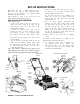
CUTTING HEIGHT ADJUSTMENT
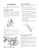
Push Modeis:
An adjusting plate and thumb lever at each wheel
position provides cutting height adjustment. Each
adjusting plate has nine height positions. Heigit of cut
will be changed when the thumb lever is moved from
one hole to another. Simply depress the lever towards
wheel and move wheel and lever assembly to desired
position. All wheels must be placed in the same rela
tive position. See figure 5A.
FIGURE 5A.—Push Models
Self-Propelled Models:
The height adjustment handles for the whisels are
located on the left side of the deck. The hancles may
be placed in one of nine cutting height positiens. See
figure 5B.
For rough or uneven lawns, move the heigh adjust
ment handles to positions which will give a hie her cut
ting height. Both front and rear handles nust be
placed in the same relative position.
HANDLE HEIGHT ADJUSTMENT
Your mower is shipped with the handle in the higher
height position. To lower the handle height, proceed
as follows.
1. Remove the starter rope from the rope guide.
2. Remove the upper handle by removing the hand
knobs and carriage bolts. Lay the upper handle
out of the way, being careful not to bend or kink
the cables.
3. Remove the hairpin clips from the weld pins on the
handle brackets. For push models, press inward
on the legs of the lower handle. Press outward on
the legs of the lower handle for self-propelled mod
els. Remove lower handle from the mower.
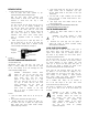
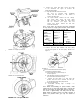
4. Turn the lower handle around so the notches on
the bottom of the lower handle are facing forward
as shown in figure 6. Reassemble, placing the
bottom holes in the handle over the weld pins in
the handle mounting bracket.
5. Reassemble the upper handle.
6. Place the hairpin clips in the inner holes in the
weld pins and attach the starter rope as instruct
ed in the Set-Up Instructions.
Lower
Handle
Notch
FIGURE 6.
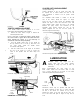
DRIVE CLUTCH CONTRDL ADJUSTMENT
(Self-Propelled Models Only)
Use the adjustment wheel located in the clutch control
housing to tighten the drive belt if mower does not self-
propel with the drive clutch control engaged, or if drive
belt is slipping (unit hesitates while engine maintains
the same speed). See figure 7.
In addition, the adjustment wheel may also be used to
determine the position in which the drive clutch control
is engaged. If it is more comfortable to have the drive
engaged with the lever further away from the handle,
tighten the drive belt.
Make certain to retest the unit for neutral as instructed
in the Operation Section. Move the adjustment wheel
in the opposite direction to loosen the drive belt if nec
essary.