
User guide

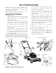
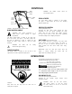
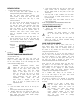
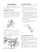
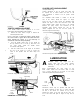
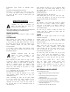
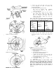
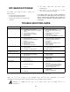

FIGURE 11.
Remove
s
FIGURE 12A.—Single Speed Models
Lower Pulley
FIGURE 12B.—Six Speed Models
6. Remove the center bolt which secures the blade
to the crankshaft. See figure 12. Remove the
blade and blade adapter.
7. A. Single Speed Models: Remove the inside
belt cover by removing three self-tapping
screws and flat washers. A 3/8” wrench is
required. See figure 12A.
B. Six Speed Models: Remove the two self-tap
ping screws which secure the lower pulley
half. See figure 12B. Rotate the lower pulley
half 90° clockwise (see figure 13A) and
remove from mower. Remove the belt from
around the crankshaft.
NOTE: If the parts are removed from the crankshaft
for any reason on single speed models, make certain
they are reassembled as shown in figure 13B.
Pulley
Halves-^i^Sk
Spring
Washer-^^;^
Flat^^^
Washer /
Spacer
Pulley
Halves«^,^.^
Spacer—
Cupped<^S
Washers ^
Pulley<<r^^X
Halves
Serrated
Washer
W ave
Washers
Briggs & Stratton
Keyed
Briggs & Stratton
Serrated (Splined)
Tecumseh
FIGURE 13B.—Single Speed Models
8. Remove the belt from between the idler pulley
and the belt guard on the idler pulley bracket. See
figure 14.
10.
B.
FIGURE 14.
9. Remove the belt from the transmission pulley.
Assemble the new belt as follows.
A. Push the idler pulley up out of the way as
shown in figure 14.
Slide the belt in from the rear of the deck, and
place it around the transmission pulley.
C. Release the idler pulley so it falls down into
position. Slide the belt in between the idler pul
ley and belt guard on the idler pulley bracket.
D. Grease the crankshaft.
E. Reassemble, following steps 1 through 7 in
reverse order.
NOTE: When reassembling six speed models, make
certain the pin on the lower pulley half is outside the
belt. On all models, be certain belt guard on transmis
sion cover is approximately 1/8" away from the belt.
Make certain to tighten all nuts and bolts securely. If
plastic was placed under gas cap, be certain to
remove it.
FIGURE 13A.—Six Speed Models