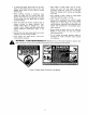
OPERATOR'S MANUAL Model Series 060 IMPORTANT: READ SAFETY RULES AND INSTRUCTIONS CAREFULLY Warning: This unit is equipped with an internaI combustion engine and should not be used on or near any unimproved forestcovered, brush-covered or grass-covered land uniess the engine's exhaust system is equipped with a spark arrester meeting applicable local or state laws (if any), if a spark attester is used, it sho[lld be maintained in effective working order by the operator.
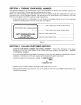
SECTION 1: FINDING YOUR MODEL NUMBER This Operator's Manual is an important part of your new walk behind. It will help you assemble, prepare and maintain your walk behind. Please read and understand what it says. Before you start to prepare your walk behind for its first use, please locate the model plate and copy the information from it in this Operator's Manual. The information on the model plate is very important if you need help from your dealer or the MTD customer support department.
SECTION 3: IMPORTANT SAFE OPERATION PRACTICES WARNING; THIS SYMBOL POINTS OUT IMPORTANT SAFETY INSTRUCTIONS WHICH, IF NOT FOLLOWED, COULD ENDANGER THE PERSONAL SAFETY AND/OR PROPERTY OF YOURSELF AND OTHERS. READ AND FOLLOW ALL INSTRUCTIONS IN THIS MANUAL BEFORE ATTEMPTING TO OPERATE YOUR LAWN MOWER. FAILURE TO COMPLY WITH THESE INSTRUCTIONS MAY RESULT IN PERSONAL INJURY. WHEN YOU SEE THIS SYMBOL, HEED ITS WARNING.
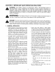
• Do netengagethe self-propelled mechanism on • Always be sure of your footing. A slip and fall can unitssoequipped whilestarting engine. cause serious personal injury. If you feel you are losing your balance release the blade control • Thebladecontrolhandle is a safetydevice. Never handle immediately and the blade will stop in less attemptto bypassitsoperation. Doingso makes than 3 seconds. the safetydeviceinoperative andmayresultin personal injurythroughcontactwiththe rotating blade.
° To reduce fire hazard, keep mower free of grass, leaves, or other debris build-up. Clean up oil or fuel spillage. Allow mower to cool at least 5 minutes before storing. • • ,_ After striking a foreign object, stop the engine, remove the wire from the spark plug, and thoroughly inspect the mower for any damage. Repair the damage before starting and operating the mower. Before cleaning, repairing, or inspecting, make certain the blade and all moving parts have stopped.
USE THIS PAGE AS A GUIDE TO DETERMINE SL ES WHERE YOU MAY NOT OPERATE SAFELY. SIGHT AND HOLD THIS LEVEL WITH A VERTICAL TREE I Ot_ A POWER POLE '411 I I A CORNER OF A BUILDING _WARNING 4/ i I-- O I&l Do not mow on inclines with a slope in excess of 15 degrees (a rise could overturn and cause serious injury, If operating a walk-behind your footing and you could slip, resulting in serious injury.
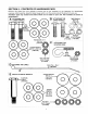
SECTION 5: CONTENTS OF HARDWARE PACK Remove this sheet from your operator's manual and lay the hardware on the illustration for identification purposes, After Assembly, keep the Slope Gauge which is on the reverse side of this sheet for future use. (Hardware pack may contain extra items which are not used on your unit. Part numbers are shown in parentheses.) ......... _t A iATTACHmG THE , LOWER HANDLE Hex B O O O O ATTACHING THE UPPER HANDLE Split Washers 5/16" I+D.
SECTION TO REMOVE 6: UNPACKING UNIT FROM CARTON • Remove staples, break glue on top flaps, or cut tape at carton end and peel along top flap to open. • Remove loose parts if included with unit (i.e., operator's manual, etc.). • Cut along dotted lines and lay carton down flat. • Remove packing material. • Slide unit out of carton. Check carton thoroughly for loose parts.
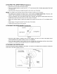
ATTACHING THE LOWER HANDLE (w!_rd_e_A_) • Raise the rear of the deck and block securely, • Place one cupped washer on each hex bolt 1-1/2" tong (crowned side of washer goes against the head of the hex belt). • Insert the ends of the lower handle through the slots in the rear of the deck. NOTE: It is helpful to have another person hold the handle in position as you continue. • Place two spacers between the bottom hole in lower handle and bottom inside hole of the deck. See Figure 4.
NOTE: If the control handle is disassembled from the upper handle for any reason, assemble the control handle by inserting the ends into the holes on each side of the upper handle. The hole in the control handle must be on the left side of the upper handle, and control handle must touch the upper handle when engaged (squeezed against the upper handle). • Remove the truss machine screw and hex lock nut from the middle of the control box using a phillips screwdriver.
INSTALLATION OF WHEELS (Hardware E) Smaller Cupped Washer Use These Holes for Front Wheels Front Wheel \ \ Axle Bolt / / Hex Nut Larger Cupped Washer Figure 9 The three holes provide three cutting heights for your mower. Use the same hole location for all four wheels when assembling. If wheels are to be assembled in the lowest cutting position (highest hole in the deck), refer to the note below.
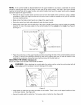
FINAL ASSEMBLY OF MOWER I Chute Deflector Shipping Chute Retainer -" ......................... Figure 11 • The chute deflector on your mower is held in an upright position by a retainer for shipping purposes only. This shipping retainer must be removed and discarded before the mower is put into operation. See Figure 1 1. To remove the shipping chute retainer, move the spring-loaded chute toward the engine by pushing above the retainer.
SECTION 9: OPERATION Keep hands and feet away from the chute area on cutting deck. See Figure 2, Warning Label. which can result in severe eye damage. Always wear objects safety glasses or eyeinto shields. We The operation of any lawn mower can result in foreign being thrown the eyes, recommend wide vision safety mask for over spectacles or standard safety glasses. GAS AND OIL FILL-UP Service the engine with gasoline and oil as instructed in the separate engine manual packed with your mower.
SECTION 10: ADJUSTMENTS engine and disconnecting plugmake wire. any adjustment to lawn mower without first stopping the WARNING: Do not at spark any time _, CUTTING HEIGHT ADJUSTMENT Adjustment may be made by removing and moving axle bolts to desired position. Cutting heights will be raised as axle bolts are moved to a lower hole and lowered as axle bolts are moved to a higher hole in the deck. All axle bolts must be mounted in the same relative position.
SECTION 12: MAINTENANCE WARNING: Be sure to disconnect and ground the spark plug wire before performing any repairs or maintenance. NOTE: When tipping the unit, empty the fuel tank and keep engine air filter side up. TROUBLE SHOOTING Refer to page 17 of this manual for trouble shooting information. CUTTING BLADE When removing the cutting blade for sharpening or replacement, protect hands by using heavy gloves or a thick rag to grasp the cutting blade.
ENGINE Refer to the separate engine manual for engine maintenance instructions. Maintain engine oil as instructed in the separate engine manual packed with your unit. Follow instructions carefully. Service air cleaner every 25 hours under normal conditions. Clean every few hours under extremely dusty conditions. Poor engine performance and flooding usually indicates that the air cleaner should be serviced. To service the air cleaner, refer to the separate engine manual packed with your unit.
SECTION Trouble [ Engine fails to start Engine erratic 14: TROUBLE runs Engine ioverheats Possibie SHOOTING causeis) Blade control handle disengaged. Spark plug wire disconnected. Dirty aircleaner. Primer button not depressed Throttle control lever not in correct starting position (if so equipped) Fuel tank empty or stale fuel. Blocked fuel line (if so equipped). Faulty spark plug. Engine flooded. Init running in START position. Spark plug wire loose.
Model Series 060 37 lO j 9 /' / / / / / 7 12 15 ,,_Jl 22 /21 _39 f 25 TO Enlgine Crankshaft 22 29_ --35 / / / 28 28 2 18
Model Series 060 RER NO. PART NO, 1 2 3 4 5 6 7 8 9 lO 11 12 13 14 15 16 17 18 19 20 710-1044 736-0524A 742-0642 748-0376C 710-0654A 682-0086 749-0928 726-0240 746-0550 749-0538C 747-0824 712-0324 746-0883 710-1270 710-1205 746-0876 710-1250 736-0119 712-0267 736-0501 DESCRIPTION Hex Bolt 3/8-24 x 1.5" Lg. Support, Bell-Blade 22" Blade, Std. Adaptor, Blade Screw: TTSems,3/8 - 16 x 1" Deck Assy, 22" Side Discharge Lower Handle Cable Tie Control Cable-39" Upper Handle Control Handle Hex L-Nut 1/4-20 Thd.
MANUFACTURER'S LIMITED WARRANTY For TWO YEARS from the date of retail purchase within the United States of America, its possessions and territories, the manufacturer will, at its option, repair or replace, for the original purchaser, free of charge, any part or parts found to be defective in material or workmanship.