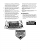
Operator's Manual 21" Rear Discharge Push Mower Model Series 410 through 419 IMPORTANT: Warning: Read safety rules and instructions This unit is equipped with an internal combustion carefully before operating equipment. engine and should not be used on or near any unimproved forest-cov- ered, brush-covered or grass-covered land unless the engine's exhaust system is equipped with a spark arrester meeting applicable local or state laws (if any).
TABLEOFCONTENTS Content Page 3 6 7 10 Important Safe Operation Practices Slope Gauge Assembling Your Lawn Mower Know Your Lawn Mower Operating Your Lawn Mower 11 Content Making Adjustments Maintaining Your Lawn Mower Troubleshooting Illustrated Parts List Page 12 13 15 16 Warranty 20 FINDINGMODELNUMBER This Operator's Manual is an important part of your new lawn mower. It will help you assemble, prepare and maintain the unit for best performance. Please read and understand what it says.
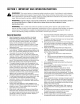
SECTION1: IMPORTANT SAFEOPERATION PRACTICES WARNING: This symbol points out important safety instructions which, if not followed, could endanger the personal safety and/or property of yourself and others. Read and follow all instructions in this manual before attempting to operate this machine. Failure to comply with these instructions may result in personal injury. When you see this symbol--HEED ITS WARNING.
unclogging thechute. Thecutting bladecontinues to rotate forafewseconds aftertheengine isshutoff. Never placeanypartofthebodyinthebladeareauntil youaresurethebladehasstopped rotating. 13. Never operate mower without proper trailshield, discharge cover, grasscatcher, bladecontrol handle or othersafety protective devices inplaceandworking. Never operate mower withdamaged safety devices. Failure todoso,canresultinpersonal injury. 14. Muffler andengine become hotandcancause aburn.Do nottouch. 15.
4. 5. 6. 7. 8. 9. fordamage (e.g.,bent,cracked, worn)Replace blade withtheoriginal equipment manufacture's (O.E.M.) blade only,listedinthismanual. "Useofpartswhichdonot meettheoriginal equipment specifications mayleadto improper performance andcompromise safetyF Mower blades aresharpandcancut.Wrapthebladeor weargloves, anduseextracaution whenservicing them. Keepallnuts,bolts,andscrews tighttobesurethe equipment isinsafeworking condition. Never tamper withsafety devices.
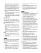
O0 m USE THIS PAGE AS A GUIDE TO DETERMINE SLOPES WHERE YOU MAY NOT OPERATE SAFELY. SIGHT AND HOLD THIS LEVEL WITH A VERTICAL A POWER I "If .J.. I I '111 I I I _ i I " FOLD I ='_ Z TREE POLE A CORNER 0^,_ --I OF A BUILDING OR A FENCE POST mo m I ,v/.jO- ..... =,'_/_ m I O c 03 > r- O z © 15 ° O --t --t I-r1 I-- _ WARNING Do not mow on inclines with a slope in excess of 15 degrees (a rise of approximately 2-1/2 feet every 10 feet).
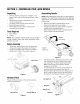
SECTION3: ASSEMBLING YOURLAWNMOWER Unpacking AssemblingHandle • Remove staples, break glue on top flaps, or cut tape at carton end and peel along top flap to open carton. • Remove loose parts if included with unit (i.e., owner's manual, etc.). Cut along corners and lay carton down flat. Remove packing material. Roll or slide unit out of carton. Check carton • • • NOTE: Stand behind the mower as if you were going to operate it.
• • • • Refer to the hardware pack in Figure 2. Insert the carriage bolt from the hardware pack into the upper hole on the handle mounting bracket. See Figure 4. Secure with one plastic wing nut, also included in the hardware pack. Repeat on the other side with remaining items from the hardware pack. The rope guide is attached to the right side of the upper handle. Loosen the wing nut which secures the rope guide.
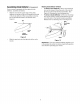
Assembling ChuteDeflector(ifequipped) If your mower is equipped with the optional chute deflector, assemble as follows: • Slide the rod into the upper edge of the chute deflector so the tab on the rod is toward the left side of the chute deflector. When assembled correctly, the rod will extend further to the left side. See Figure 9. Tab Rod AttachingChuteDeflectorTo Mower • • To attach chute deflector: Lift the rear discharge door on the mower.
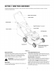
SECTION4: KNOWYOURLAWNMOWER Compare the illustrations in Figure 11 with your lawn mower to familiarize yourself with the location of various controls and adjustments. Blade Control Handle Upper Handle Recoil Starter Bag-Fill Indicator (if equipped) Lower Handle Grass Catcher Oil Fill/Dipstick / /-- Spark Plug Gasoline Fill Cutting Height Adjustment Lever (Only two of four are called out.
SECTION5: OPERATING YOURLAWNMOWER ToStopEngine& Blade ,_ from the chute area cutting Refer to WARNING: Keep on hands anddeck. feet away warning label on the unit. • • GasandOilFill-Up • Service the engine with gasoline and oil as instructed in the engine manual packed with your mower. Read instructions carefully. ,_ UsingRotaryMower _ WARNING" Never fill or the(iii) fuelif engine tank (i) has indoors, (ii) with engine running, not sufficiently cooled down.
SECTION6: MAKINGADJUSTMENTS on the handle brackets. Attach the starter rope as instructed in the Assembly section. _ ARNING"to lawn Do not at any time make adjustment mower without first any stopping the engine and disconnecting the spark plug wire. CuttingHeight An adjusting plate and thumb lever at each wheel position provides cutting height adjustment. Each adjusting plate has nine height positions. HandleHeight The mower is shipped with the handle at a higher height position.
SECTION7: MAINTAININGYOURLAWNMOWER BladeMountingTorque: Center Bolt: 450 in. Ibs. min., 600 in. Ibs. max. _ ARNING" Beplug surewire to disconnect and ground the spark before performing any repairs or maintenance. IMPORTANT: To ensure safe operation of your unit, periodically check all nuts and bolts and tighten if necessary. MaintainingtheBlade • _i DeckCare Periodically inspect the blade adapter for cracks, especially if the mower strikes a foreign object.
• • BladeControl Clean spark plug and reset the gap once a season. Spark plug replacement is recommended at the start of each mowing season. Check engine manual for correct plug type and gap specifications. Clean engine regularly with a cloth or brush. Keep the cooling system (blower housing area) clean to permit proper air circulation. Remove all grass, dirt and combustible debris from muffler area.
SECTION8: TROUBLE SHOOTING GUIDE Trouble Possible Cause(s) Corrective Actions Engine fails to start 1. 2. 3. 4. 5. 1. 2. 3. 4. 5. Engage blade control handle. Connect wire to spark plug. Refer to the engine manual. Refer to the engine manual. Move throttle lever to FAST or START position. 6. 7. 8. 9. Blade control handle disengaged. Spark plug wire disconnected. Dirty aircteaner. Primer button not depressed. Throttle control lever (if so equipped) not in correct starting position.
SECTION9: PARTSLISTFORMODELSERIES410THROUGH 419 11 \ lo_. /2 20 16 21 22 34 48 \54 Zag Tread Wheel 22 Bar Tread Wheel 16
ModelSeries410Through419 Ref. No. 1. 2. 3. 7. 8. 9. 10. 11. 12. 13. 14. 15. 16. 17. 18. 19. 20. 21. 22. 23. 24. 25. 26. 27. 28. 29. 30. 31. 32. Part No. 747-1161A 749-1092A 747-04080 749-0928A 720-0279 710-1205 710-1174 664-04005 764-0650 720-0284 736-0451 726-0240 710-0703 731-04134 750-04162 732-04089 732-04090 787-01144 787-01143 $ 782-5003 731-0981A 787-01103 710-1017 782-5002A 748-0376C 742-0741 710-1044 736-0524A 15261A 687-02077 687-02077 687-02076 687-02076 720-0426 Ref. No. 33. 34. 36. 38. 39.
YOURNOTES Date Comments 18
YOURNOTES Date Comments 19
MANUFACTURER'S LIMITED WARRANTY The limited warranty set forth below is given by MTD LLC with respect to new merchandise purchased and used in the United States, its possessions and territories. "MTD"warrants this product against defects in material and workmanship for a period of two (2) years commencing on the date of original purchase and wilt, at its option, repair or replace, free of charge, any part found to be defective in materials or workmanship.