® Operator’s Manual 21” Rear & Side Discharge Mulching Mower Model Number 11A-545D034 IMPORTANT: READ SAFETY RULES AND INSTRUCTIONS CAREFULLY Warning: This unit is equipped with an internal combustion engine and should not be used on or near any unimproved forestcovered, brush-covered or grass-covered land unless the engine’s exhaust system is equipped with a spark arrester meeting applicable local or state laws (if any).
TABLE OF CONTENTS Content Page Important Safe Operation Practices................................................................... 3 Slope Gauge...................................................................................................... 6 Assembling Your Lawn Mower........................................................................... 7 Know Your Lawn Mower .................................................................................... 9 Operating Your Lawn Mower .....................
SECTION 1: IMPORTANT SAFE OPERATION PRACTICES WARNING: This symbol points out important safety instructions which, if not followed, could endanger the personal safety and/or property of yourself and others. Read and follow all instructions in this manual before attempting to operate this machine. Failure to comply with these instructions may result in personal injury. When you see this symbol - heed its warning.
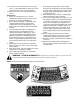
9. 10. 11. 12. 2. continues to rotate for a few seconds after the engine is shut off. Never place any part of the body in the blade area until you are sure the blade has stopped rotating. Never operate mower without proper trail shield, discharge cover, grass catcher, blade control handle or other safety protective devices in place and working. Never operate mower with damaged safety devices. Failure to do so, can result in personal injury. Muffler and engine become hot and can cause a burn.
7. After striking a foreign object, stop the engine, disconnect the spark plug wire and ground against the engine. Thoroughly inspect the mower for any damage. Repair the damage before starting and operating the mower. 8. Never attempt to make a wheel or cutting height adjustment while the engine is running. 9. Grass catcher components, discharge cover, and trail shield are subject to wear and damage which could expose moving parts or allow objects to be thrown.
SECTION 2: SLOPE GAUGE Use this page as a guide to determine slopes where you may not operate safely. Do not operate your lawn mower on such slopes. FOL D ON D OTT ED L IN E 15° , S EN TI NG A 15 ° SL O PE OR A FENCE POST A CORNER OF A BUILDING A POWER POLE SIGHT AND HOLD THIS LEVEL WITH A VERTICAL TREE R EP RE WARNING Do not mow on inclines with a slope in excess of 15 degrees (a rise of approximately 2-1/2 feet every 10 feet). A riding mower could overturn and cause serious injury.
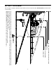
SECTION 3: ASSEMBLING YOUR LAWN MOWER IMPORTANT: This unit is shipped without gasoline or oil in the engine. Be certain to service engine with gasoline and oil as instructed in the separate engine manual before operating your mower. NOTE: Reference to right or left hand side of the mower is observed from the operating position. Removing Unit From Carton • • • • Remove staples, break glue on top flaps, or cut tape at carton end and peel along top flap to open carton.
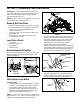
Attaching Rear Wheels • • • • Remove hardware from hardware pack. Insert shoulder screw through wave washer, flat washer, rear wheel, and spring washer. Secure shoulder screw with hardware to rear pivot bar. See Figure 5. Secure bag to frame by working the plastic channels on bag over frame as shown in Figure 7B. All of the plastic channels except the center top of the bag attach from the outside of bag. The center top of the bag attaches from inside the bag.
Attaching Grass Catcher To Mower Removing Grass Catcher • • Lift the rear discharge door and place the grass catcher on the pivot rod. Let go of discharge door so that it rests on the grass catcher. See Figure 9. Lift the rear discharge door on the mower, and lift the grass catcher up. Release the rear discharge door. • Converting To Side Discharge • Your mower has been shipped as a mulcher. To convert it to a side-discharge mower, lift the mulching plug.
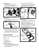
Mulching Plug Cutting Height Adjustment Levers The mulching plug is used only for mulching purposes. Instead of collecting the grass clippings in a grass catcher, some mower models have the option of recirculating the clippings back to the lawn. See Figure 11. These levers are located on each wheel and are used to adjust the cutting height. These levers have to be at the same relative position to ensure uniform cut.See Figure 11.
Using Your Lawn Mower WARNING: If you strike a foreign object, stop the engine. Remove wire from the spark plug, thoroughly inspect the mower for any damage, and repair the damage before restarting and operating the mower. Extensive vibration of the mower during operation is an indication of damage. The unit should be promptly inspected and repaired. Be sure that the lawn is clear of stones, sticks, wire, or other objects which could damage the lawn mower or the engine.
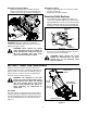
IMPORTANT: All wheels must be placed in the same Height Adjustment Lever relative position. For rough or uneven lawns, move the height adjustment lever to a higher position. This will help stop scalping of the grass. Engine Adjustments See the separate engine manual packed with your unit for adjustments to the engine. Figure 13 SECTION 7: MAINTAINING YOUR LAWN MOWER General Recommendations • • Some adjustments will have to be made periodically to maintain your unit properly.
Lubrication Always stop engine and disconnect spark plug wire before cleaning, lubricating or doing any kind of service work on the lawn mower. Rear Discharge Door Handle Bracket Blade Control: Lubricate the pivot points on the blade control handle and the brake cable at least once a season with light oil. The blade control must operate freely in both directions. See Figure 14.
• • Remove the blade and the adapter from the crankshaft. Blade Adapter • • Blade Bell Support • Hex Bolt • Be sure to install the blade with the side of the blade marked “Bottom” (or with part number) facing the ground when the mower is in the operating position. Slide the blade adapter onto the engine crankshaft. Place the blade on the adapter. Be certain the blade is aligned and seated on the blade adapter flanges. Place blade bell support on blade.
SECTION 8: TROUBLESHOOTING Problem Cause Remedy Blade control handle disengaged. Spark plug wire disconnected. Fuel tank empty or stale fuel. Blocked fuel line. Faulty spark plug. Engine flooded 1. Engage blade control handle. 2. Connect wire to spark plug. 3. Fill tank with clean, fresh gasoline. 4. Clean fuel line. 5. Clean, adjust gap, or replace. 6. Wait a few minutes to restart, but do not prime. Engine fails to start 1. 2. 3. 4. 5. 6. Engine runs erratic 1. Spark plug wire loose. 2.
Model 545 68 1 2 65 64 9 3 63 10 4 11 8 6 5 19 7 12 13 18 28 61 57 41 59 14 30 15 20 17 16 40 60 33 21 24 35 34 25 19 22 23 38 39 31 62 32 36 37 29 44 45 27 53 36 47 42 43 26 52 46 48 54 55 69 49 35 67 58 56 50 41 51 66 16
Model 545 Ref. No. 1. 2. 3. 4. 5. 6. 7. 8. 9. 10. 11. 12. 13. 14. 15. 16. 17. 18. 19. 20. 21. 22. 23. 24. 25. 26. 27. 28. 29. 30. 31. 32. 33. 34. 35. Part No. 749-1092A Ref. No. Part Description Upper Handle 747-1161A Control Handle 720-0279 Handle Knob 710-1205 Rope Guide 710-1174 Carriage Bolt 5/16-18 x 2” 736-0451 Shoulder Washer.320 ID x.
MANUFACTURER’S LIMITED WARRANTY FOR: ® The limited warranty set forth below is given by MTD LLC with respect to new merchandise purchased and used in the United States, its possessions and territories. MTD LLC warrants this product against defects for a period of two (2) years commencing on the date of original purchase and will, at its option, repair or replace, free of charge, any part found to be defective in materials or workmanship.
® Manual del operador Descarga posterior y lateral 21” Podadora abonadora Número de modelo 11A-545D034 IMPORTANTE: LEA CON ATENCIÓN LAS REGLAS DE SEGURIDAD E INSTRUCCIO ADVERTENCIA: Esta unidad está equipada con un motor de combustión interno y no debe ser utilizada en o cerca de un terreno agreste cubierto por bosque, malezas o hierba excepto que el sistema de escape del motor esté equipado con un amortiguador de chispas que cumpla con las leyes locales o estatales correspondientes (en caso de existir).
ÍNDICE Contenido Página Medidas importantes de seguridad.................................................................... 3 Indicador de pendiente ...................................................................................... 6 Montaje de su máquina podadora...................................................................... 7 Conozca las propiedades de la podadora.......................................................... 9 Funcionamiento de la podadora........................................
SECCIÓN 1: MEDIDAS IMPORTANTES DE SEGURIDAD ADVERTENCIA: Este símbolo indica importantes instrucciones de seguridad las cuales, en caso de no ser respetadas, podrían poner en peligro la seguridad del personal y/o sus bienes materiales y los de terceros. Lea y siga todas las instrucciones contenidas en este manual antes de intentar poner esta máquina en funcionamiento. De no hacerlo puede ocasionar lesiones. Cuando encuentre este símbolo - respete la advertencia que aparece a continuación del mismo.
9. 10. 11. 12. 2. cuchilla continua girando por unos cuantos segundos después que el motor se ha apagado. Nunca coloque ninguna parte del cuerpo en el área de la cuchilla hasta que esté seguro que la cuchilla ha detenido su movimiento rotatorio. Nunca opere la cortadora sin las guardas apropiadas, cubierta de descarga, guarda para recorte, manija de control de la cuchilla y otros dispositivos de seguridad y protección en su lugar y funcionando.
5. Mantenga todos los pernos, tuercas y tornillos bien ajustados para asegurarse que la máquina se encuentra en condiciones seguras de operación 6. Nunca manipule los dispositivos de seguridad de manera imprudente. Controle periódicamente que funcionen de forma adecuada. 7. Después de golpear con algún objeto extraño, detenga el motor, desconecte el cable de la bujía y conecte el motor a masa. Inspeccione minuciosamente para ver si la máquina está dañada. Repare el daño antes de arrancar y operar. 8.
SECCIÓN 2: INDICADOR DE PENDIENTE Use esta página como una guía para determinar las inclinaciones de las pendientes en las que podría no tener una operación segura. No opere su podadora en dichas pendientes.
SECCIÓN 3: ENSAMBLAJE DE SU PODADORA IMPORTANTE: Esta unidad se envía sin gasolina ni aceite en el motor. Antes de operar la máquina cargue el motor con gasolina y aceite como se indica en el manual del motor. NOTA: Las referencias a los lados derecho o izquierdo de la podadora se hacen observando la máquina desde la posición de operación.
Unión de ruedas traseras • • • muestra en Figura 7B. Todos los canales de plástico, excepto el central superior de la bolsa se unen desde afuera de la bolsa. La parte central superior de la bolsa se une desde adentro. Retire el hardware del paquete. Inserte el tornillo de hombro a través de la arandela ondulada, la arandela, la rueda trasera y la arandela de resorte. Sujete el tornillo con el hardware a la barra pivote trasera. Ver Figura 5.
Unión de la tolva para recorte con la podadora Retiro de la tolva para recorte • • Levante la puerta de descarga posterior y coloque la tolva para recorte en la barra de pivote. Descanse la puerta de descarga en la tolva para recorte de césped. Ver Figura 9. • Levante la puerta de descarga posterior y levante la tolva para recorte. Libere la puerta de descarga posterior. Conversión a descarga lateral • Su podadora ha sido enviada como abonadora.
Palanca de ajuste de la altura de corte El adaptador para la abonadora se usa únicamente para este propósito. En vez de recolectar los recortes del césped en la tolva para recortes, algunos modelos tienen la opción de recircular los recortes en el césped. Ver Figura 11. Estas palancas se localizan en cada rueda y se usan para ajustar la altura de corte. Estas palancas deben estar al mismo nivel relativo para garantizar un corte uniforme. Ver Figura 11.
Uso de su podadora ADVERTENCIA: Si golpea un objeto extraño, detenga el motor. Retire el cable de la bujía, inspeccione la podadora para ver que no tenga daños y repare el daño antes de reiniciar y operar la podadora. Si la podadora vibra mucho durante su funcionamiento es indicativo de que está dañada. Esta unidad deberá repararse e inspeccionarse cuanto antes. Asegúrese que el césped está libre de piedras, palos, cables u otros objetos que pudiesen dañar la cortadora o el motor.
IMPORTANTE: Todas las ruedas deben ser colocadas en la misma posición relativa. Para céspedes duros o disparejos, mueva la palanca de ajuste a una posición más alta. Esto ayudará a detener el desgaste del césped. Ajuste de la altura Palanca Ajustes al motor Remítase al manual del motor, que está empacado con su unidad por separado para obtener información acerca de los ajustes al motor.
Lubricación Detenga siempre el motor y desconecte el cable de la bujía antes de limpiar y lubricar la máquina o de realizar todo tipo de mantenimiento de la misma. Descarga posterior Puerta Manija Soporte Control de la cuchilla Lubrique los puntos de pivote de la manija de control de la cuchilla y el cable de frenos al menos una vez cada estación con aceite ligero. El control de la cuchilla debe funcionar libremente en ambas direcciones. Ver Figura 14.
• • Hoja Adaptador • Campaña de la cu Sostén • Bulón hexagonal NOTA: Para asegurar una operación segura de su podadora, el bulón de la cuchilla debe revisarlo periódicamente para ver que esté correctamente apretado. Figura 16 ADVERTENCIA: Inspeccione periódicamente el adaptador de la cuchilla en busca de cuarteaduras, especialmente cuando golpee un objeto extraño. Reemplace cuando sea necesario. Almacenamiento de su podadora Debe realizar los siguientes preparativos antes de almacenar su podadora.
SECCIÓN 8: GUÍA PARA LA SOLUCIÓN DE PROBLEMAS Problema Causa Solución El motor no arranca 1. Manija de control de la cuchilla desenganchada 2. Se ha desconectado el cable de la bujía. 3. El tanque de combustible está vacío o el combustible es viejo. 4. La línea del combustible está bloqueada. 5. La bujía no funciona correctamente. 6. Motor inundado 1. Enganche la manija de control de la cuchilla. 2. Conecte el cable a la bujía. 3. Llene el tanque con gasolina limpia y fresca. 4.
Modelo 545 68 1 2 65 64 9 3 63 10 4 11 8 6 5 19 7 12 13 18 28 61 57 41 59 14 30 15 20 17 16 40 60 33 21 24 35 34 25 19 22 23 38 39 31 62 32 36 37 29 44 45 27 53 36 47 42 43 26 52 46 48 54 55 69 49 35 67 58 56 50 41 51 66 16
Modelo 545 No. de Ref. 1. 2. 3. 4. 5. 6. 7. 8. 9. 10. 11. 12. 13. 14. 15. 16. 17. 18. No. de parte No. de Ref. Descripción de la parte 749-1092A Manija superior 747-1161A Manija de control 720-0279 Perilla manual 710-1205 Guía de cuerda 710-1174 Bulón del carro, 5/16-18 x 2” 736-0451 720-0284 Arandela de hombro .320 ID x .930 OD Tuerca alada 749-0928A Manija inferior 35. 36. 37. 38. 39. 40.
GARANTÍA LIMITADA DEL FABRICANTE PARA: ® La garantía limitada que se extiende a continuación es otorgada por la empresa MTD LLC y cubre mercaderías nuevas compradas y utilizadas en los Estados Unidos, sus posesiones y territorios. MTD LLC garantiza este producto por defectos materiales y de fabricación por un período de dos (2) años a partir de la fecha de la compra original y reparará o cambiará sin cargo cuando lo considere pertinente todas las piezas con defectos materiales o de fabricación.