Operator's Manual 21" Mulching Mower Series 540 Warning: This unit is equipped with an internal combustion engine and should not be used on or near any unimproved forest-cov- ered, brush-covered or grass-covered land unless the engine's exhaust system is equipped with a spark arrester meeting applicable local or state laws (if any). If a spark arrester is used, it should be maintained in effective working order by the operator.
TABLEOFCONTENTS Content Page 3 6 7 9 Important Safe Operation Practices Slope Guage Assembling Your Lawn Mower Know Your Lawn Mower Operating Your Lawn Mower Making Adjustments 10 11 Content Maintaining Your Lawn Mower Servicing Your Mower Troubleshooting Illustrated Parts List Page 12 12 13 14 Warranty 16 FINDINGMODELNUMBER This Operator's Manual is an important part of your new lawn mower. It will help you assemble, prepare and maintain the unit for best performance.
SECTION1: IMPORTANT SAFEOPERATION PRACTICES WARNING" This symbol points out important safety instructions which, if not followed, could endanger the personal safety and/or property of yourself and others. Read and follow all instructions in this manual before attempting to operate this machine. Failure to comply with these instructions may result in personal injury. When you see this symbol--HEED ITS WARNING.
immediately andthebladewillstoprotatingwithin 3. Do not mow on wet grass. Unstable footing could threeseconds. cause slipping. 9. Mowindaylightorgoodartificiallight;walk,notrun. 10.Stopthebladewhencrossinggraveldrives, Children walkwaysorroads. accidents can occur if the operator is not alert to 11.Iftheequipment shouldstarttovibrateabnormally, Tragic the presence of children. Children are often attracted to stoptheengineandcheckimmediately forthe the mower and the mowing activity. They do not cause.
10.Neveroverfillfueltank.Filltanktonomorethan½ inchbelowbottomoffillernecktoprovidespacefor fuelexpansion. 11.Replacegasolinecapandtightensecurely. 12.If gasolineisspilled,wipeitofftheengineand equipment. Moveunittoanotherarea.Wait5 minutesbeforestartingtheengine. 13.Neverstorethemachineorfuelcontainer inside wherethereisanopenflame,sparkor pilotlightas ona waterheater,spaceheater,furnace,clothes dryerorothergasappliances. 14.Toreducefirehazard,keepmowerfreeofgrass, leaves,orotherdebrisbuild-up.
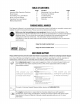
o E SIGHT AND HOLD THIS LEVEL WITH A VERTICAL TREE i,,II t- A POWER POLE I O A CORNER OF A BUILDING I OR A FENCE POST QI O cO r_ d) o *6 r- E cO o (D I rd) o 15 ° t,D o(D ,iI "_ WARNING O3 64 o Do not mow on inclines with a slope in excess of 15 degrees (a rise of approximately 2-1/2 feet every 10 feet). A riding mower could overturn and cause serious injury.
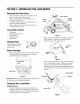
SECTION3: ASSEMBLING YOURLAWNMOWER RemovingUnitFromCarton • • • • Remove staples, break glue on top flaps, or cut tape at carton end and open carton. Remove loose parts if included with unit (i.e., operator's manual, etc.) Cut along corners, lay the carton down flat, and remove all packing material. Roll or slide unit out of carton and check carton Lower Handle Handle Upper Handle },_acket thoroughly for loose parts.
• • After moving the hairpin clip, insert the carriage bolt, from the hardware pack, in the upper hole on the handle mounting bracket and secure with plastic wing nut from the hardware pack. See Figure 4. Repeat on the other side. Fasten the cable to the lower handle with the two cable ties found on the lower handle. Pull the cable ties tight and trim off the excess. See Figure 5. • • AssemblingGrassCatcher NOTE: If the grass catcher came pre-assembled, proceed to the next section.
IMPORTANT: Makesurecableisroutedtotheoutsideof thehandlesothatitisnotinthewaywhenattaching the grasscatcher. Liftthereardischarge dooronthemower. Placethehooks,foundonbothsidesofthegrass catcherframe,overthechutedoorpivotrodatthe rearofthemower.Release thereardischarge door. SeeFigure9. Rear Discharge Door AttachingSide-Discharge Chute • Remove the grass catcher and let the discharge door close.
Read this operator's manual and safety rules before operating your lawn mower. Compare the illustration in Figure 11 with your lawn mower to familiarize yourself with the location of various controls and adjustments. Save this manual for future reference. ,_ Cutting HeightAdjustmentLevers These levers are located on each wheel and are used to adjust the cutting height. These levers have to be at the same relative position to ensure uniform cut.
StoppingEngine Mulching • Release blade control handle to stop the engine and the blade. • Disconnect spark plug wire and move away from spark plug to prevent accidental starting. For effective mulching, do not cut wet grass. New or thick grass may require a narrower cut. If the grass has grown in excess of 4", mulching is not recommended. Mow using the side discharge to reduce the grass height to 3.25" maximum before mulching.
SECTION7: MAINTAININGYOURLAWNMOWER • ,i_ WARNING" the Always stopwire the before engine and disconnect spark plug performing any maintenance work or adjustments on your lawn mower. Lubrication BladeControl Handle CleaningMower • The underside of the mower deck should be cleaned after each use to prevent any build-up of grass clippings, leaves, dirt, or other debris. • ,_ • Lubricate the pivot points on the blade control handle at least once a season with light oil.
Sharpening the Blade • • The blade can be sharpened with a file or on a grinding wheel. Do not attempt to sharpen the blade while it is still on the mower. • • Follow the original angle of grind as a guide. Make sure that each cutting edge receives an equal amount of grinding to prevent an unbalanced blade. • ,_ NOTE: To ensure safe operation of your mower, periodically check the blade bolt for correct torque.
SECTION10: PARTSLISTFORSERIES540 2 \ 13 / 4 5 2 11 / 9 31 16 34 \\ \ 19 24 23 49 37 51 50 56 14 / /
Series540 Ref, No, Part No. 1. 749-1092A 2. Ref. No, Part Description Part No. Part Description 33. 712-3005 747-1161A Upper Handle Control Handle 34. 710-0703 Hex Carriage Screw 1/4-20 3. 710-1270 C-Sunk Screw 1/4-20 x 1.3" 35. 687-02033 Handle Bracket Assembly -- RH 4. 5. 746-0883 712-0324 Throttle Housing Hex Lock Nut 1/4-20 36. 687-02031 710-1652 Handle Bracket Assembly -- LH TT Screw 1/4-14 x .625 6. 720-0279 Handle Knob 37. 710-0216 Hex Screw 3/8-16 x 0.75 7.
MANUFACTURER'S LIMITED WARRANTY The limited warranty set forth below is given by MTD LLC with respect to new merchandise purchased and used in the United States, its possessions and territories. "MTD"warrants this product against defects in material and workmanship for a period of two (2) years commencing on the date of original purchase and wilt, at its option, repair or replace, free of charge, any part found to be defective in materials or workmanship.