Safe Operation Practices • Set-Up • Operation • Maintenance • Service • Troubleshooting OPER roR's • Warranty L Push Mower m Model Series 540 MTD LLC, P.O. BOX 361131 CLEVELAND, OHiO 44136-0019 PrintedIn USA FormNo.
1 ToTheOwner ThankYou Thank you for purchasing a Lawn Mower manufactured by This product has met the rigid safety standards Power Equipment Institute and an independent MTD LLC. It was carefully engineered to provide excellent performance when properly operated and maintained. Please read this entire It instructs maintain persons manual prior to operating you how to safely and easily set up, operate your machine. laboratory.
2 importantSafeOperationPractices WARNING: This symbol could endanger points the personal all instructions safety and/or in this manual with these instructions out important before property attempting may result in personal When you see this symbol. safety instructions of yourself to operate which, if not followed, and others. this machine. Read and follow Failure to comply injury.
12. Amissing ordamaged discharge cover cancause blade contact orthrown object injuries. 13. Many injuries occur asaresult ofthemower beingpulled overthefootduring afallcaused byslipping ortripping. Donotholdontothemower ifyouarefalling; release the handle immediately. 14. Never pullthemower back toward youwhileyouare walking. Ifyoumustback themower away fromawallor obstruction firstlookdownandbehind toavoidtripping andthenfollowthese steps: a. Stepback frommower tofullyextend yourarms. b.
Service 3. Check the blade and engine intervals To avoid personal care in handling injury or property damage gasoline. Gasoline can ignite. is extremely flammable original Wash your skin and change clothes Use only an approved 3. Never fill containers gasoline container. inside a vehicle 4. Remove gas-powered equipment from Keep all nuts, bolts, and screws tight to be sure the equipment container, rather than from a gasoline Keep the nozzle in contact container opening 7.
SparkArrestor AverageUsefulLife According _ Products Safety Commission (CPSC) and the U.S. Environmental Protection Agency (EPA), this product has an Average Useful Life of seven (7) years, or 140 exhaust system is equipped a new machine or have the machine inspected annually by an authorized service dealer to ensure that all mechanical and meeting applicable with a spark arrester local or state laws (if any).
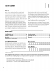
Sight and hold this level with a vertical tree... or a corner of a building... I I | ! ! ! !-- Z 0 0 ! ! !-Z i I ¢N Z 0 i I- ! | 15 ° Usethis page as a guide to determine slopeswhere you may not operate safely. WARNING: Do not operate (a rise of approximately mowers up and down up and down slopes. your lawn mower on such slopes. Do not mow on inclines with a slope in excess of 15 degrees 2-1/2 feet every 10 feet).
3 Assembly& Set-Up Contents of Carton One Lawn Mower One Lawn Mower One GrassCatcher One Engine Operator's Operator's One Bottle Manual of Oil One Hardware Manual Pack One Side Discharge Chute Assembly NOTE:This unit is shipped 2. without gasoline or oil in the engine. Fill up gasoline and oil as instructed in the accompanying manual BEFORE operating your mower. engine Locate the hairpin clip on the weld pin on each side of lower handle. a. Remove hairpin clip from this hole.
3. The rope guide is attached handle. to the right side of the upper See Fig. 3-3. Loosen the wing nut which secures the 1. Place rear of the mower 2. Remove lock nut from pivot arm assembly (on select models, in a plastic bag). rope guide. deck on raised blocks. these may be included 3. Slide wheel, with hollow with lock nut. 4. Assemble the other separately side in, onto pivot arm and secure side in the same manner.
2_ Follow the steps below to attach the grass catcher: a. Lift rear discharge 2_ Slide two hooks of side discharge mulching door. See Fig. 3-6. plug assembly. remove side mulching not mulching. chute under hinge pin on Lower the mulching plug. Do not plug at any time, even when you are Adjustments CuttingHeight Each wheel has a height adjustment height of the mower. 1. Depress height adjustment 2. Slide lever to desired height. lever to change lever towards position the cutting wheel.
4 Controls andFeatures Recoil Starter Grass Catcher Side Discharge Chute Plug Cutting Height Adjustment Levers J Figure 44 Blade Control GrassCatcher The blade control is attached to the upper handle of the mower. Depress and squeeze it against the upper handle to operate the The grass catcher, located at the rear of the mower, is used to bag the grass clippings for disposal at another site. Once the bag is unit. Release itto stop engine and blade.
5 Operation f Starting Engine WARNING: Be sure no one other than the operator engine or operating mower. Never run engine is standing near the lawn mower while starting indoors or in enclosed, poorly ventilated areas. Engine exhaust contains odorless and deadly carbon monoxide, loose clothing away from any moving engine and lawn mower. Follow the set of instructions engine manual an gas. Keep hands, feet, hair and pertaining parts on to your unit. Refer to for help with the engine.
UsingYourLawnMower UsingGrassCatcher Be sure lawn is clear of stones, sticks, wire, or other objects You can use the grass catcher to collect operating the mower. which could damage be accidently thrown serious personal _ lawn mower or engine.
6 Maintenance& Adjustments Maintenance 2. Lubricate motor General Recommendations Always observe maintenance. The warranty safety rules when performing does not cover items that the torsion spring and pivot discharge door and side mulch plug periodically oil to prevent 4. Changing DeckCare of engine-governed speed will void engine warranty. be checked A Follow the accompanying schedule and instruction and make sure these are 1.
Engine Care ReplacingRearFlap A list of key engine maintenance performance accompanying Maintain by the mower jobs required for good 1. is given below. Follow the engine manual for a detailed oil level as instructed list and instructions. in engine manual. Service air cleaner every 25 hours under Clean every few hours under extremely normal To remove rear flap, lift rear door, and press flap in on either side to remove from hole. See Fig. 6-2. r conditions. .......... ! dusty conditions.
7 Service Blade Care WARNING: sharpening When removing or replacement, the cutting protect blade for your hands with a pair of heavy gloves or use a heavy rag to hold the blade. Periodically inspect the blade adapter for cracks, especially strike a foreign object. Replace when necessary. below for blade service. 1. 5. if you blade and the blade adapter to the engine the engine crankshaft part number) which operating See faces the ground position.
Troubleshooting Problem Engine Fails to start Cause ]. Remedy Blade control disengaged. 1. Engage blade control. 2. Spark plug boot disconnected. 2. Connect w_re to spark boot. 3. Fuel tank empty or stale fuel. 3. Fill tank with clean, fresh gasoline. 4. Engine not primed (if equipped with primer). 4. Prime engine as instructed section. 5. Faulty spark plug. 5. Clean, adjustgap, 6. Blocked fuel line. 6. Clean fuel line. 7. Engine flooded. 7. Waita in the Operation or replace.
ModelSeries540 38 47 44 .
ModelSeries540 Ref I Part Number NO, 1. 747-1161A Ref [ Part Number Description I NO, Description I Blade Control 734-1988 Front Wheel, 7 x 1.8, Bar Front Wheel, 8 x 1.8, Bar 2. 749-I092A Upper Handle 734-1987 3. 746-0957 Control Cable, 37.25" 734-2005A Front Wheel, 8 x 2.125, Zag 746-1130 Control Cable, 40" 734-04087 Front Wheel, 8 x 1.8, Pin Bar 28. 738-04266 Shoulder 746-04104 Control 4. 726-0240 Cable Tie 29. 732-0404 Front Spring Lever 5.
MANUFACTURER'S LiMiTED WARRANTY The limited warranty set forth below is given by MTD LLC with respect to new merchandise purchased and used in the United States and/or its territories and possessions, and by MTD Products Limited with respect to new merchandise purchased and used in Canadaand/ or its territories and possessions (either entity respectively, "MTD").