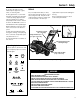
OWNER’S MANUAL 7HP PONY® REAR-TINE TILLER SAFETY FIRST! Before operating this equipment, read this Owner's Manual and the separate manual supplied by the engine manufacturer.
Table of Contents Dear Owner: You now own one of the finest standard-rotating-tine tillers available. Your new PONY® Model tiller allows you to till and cultivate your garden with ease, and accomplish dozens of other property management projects as well. Your tiller is famous for its ruggedness, performance and high-quality engineering. We know you’ll enjoy using it. Please carefully read this Manual. It tells you how to safely and easily assemble, operate and maintain your machine.
Section 1 Safety SPARK ARRESTER WARNING TO RESIDENTS OF CALIFORNIA AND SEVERAL OTHER STATES Under California law, and under the laws of several other states, you are not permitted to operate an internal combustion engine using hydrocarbon fuels on any forest, brush, hay, grain, or grass covered land; or land covered by any flammable agricultural crop without an engine spark arrester in continuous effective working order.
Section 1: Safety 7. Take all possible precautions when leaving the machine unattended. Stop the engine. Remove ignition key on electric start models. Disconnect spark plug wire and move it away from the spark plug. Move Wheel Gear Lever to ENGAGE. 8. Before cleaning, repairing, or inspecting, stop the engine, remove the ignition key on electric start models, and make certain all moving parts have stopped.
Section 1: Safety 4. To reduce the chances of a fire hazard, keep the engine free of grass, leaves, or excessive grease. 5. Store gasoline in a cool, well-ventilated area, safely away from any sparkor flame-producing equipment. Store gasoline in an approved container, safely away from the reach of children. 6. Refer to the Maintenance section of this Manual and in the separate Engine Owner’s Manual for instructions if the tiller is to be stored for an extended period. 7.
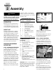
Section 2 Assembly WARNING To prevent personal injury or property damage, do not start the engine until all assembly steps are complete and you have read and understand the safety and operating instructions in this Manual. INTRODUCTION Carefully follow these assembly steps to correctly prepare your tiller for use. It is recommended that you read this Section in its entirety before beginning assembly. INSPECT UNIT Inspect the unit and carton for damage immediately after delivery.
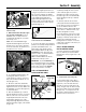
Section 2: Assembly M C E F B Figure 2-3: Forward clutch control cable not shown for clarity. 3. With forward clutch cable (N, Figure 2-4) on inside of handlebar, position handlebar ends on outside of the two mounting tabs (M, Figure 2-3) on transmission top cover. NOTE: The curved handlebar height adjustment bracket appears as shown in C, Figure 2-3 for non-electric start units. For electric start units, the bracket is loosened and moved to one side. C P N O Figure 2-4: Attach handlebars. 5.
Section 2: Assembly STEP 5: CHECK TRANSMISSION GEAR OIL LEVEL The transmission was filled with gear oil at the factory. However, be sure to check the oil level at this time to make certain it is correct. R IMPORTANT: Do not operate the tiller if the gear oil level is low. Doing so will result in severe damage to the transmission components. Completed Connection Figure 2-8: Forward clutch control spring connection to forward control linkage. 1.
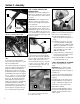
Section 2: Assembly STEP 7: ATTACH WHEEL GEAR LEVER STEP 8: CHECK AIR PRESSURE IN TIRES 1. Insert the Wheel Gear Lever (P, Figure 2-13) up through the slot in the control panel that is labeled “WHEEL GEAR.” Use a tire pressure gauge to check the air pressure in both tires. Deflate or inflate both tires equally to 15-to-20 PSI (pounds per square inch). Be sure that both tires are inflated equally or the unit will pull to one side. 2.
Section 2: Assembly Electric Start Assembly Steps The following steps explain how to prepare and install the battery. FOR YOUR SAFETY, CAREFULLY FOLLOW ALL STEPS AND OBSERVE ALL ACCOMPANYING SAFETY MESSAGES. Before beginning, check that you have received the following items (see Figure 2-16): 1. Battery (installed on tiller) 2. Clear plastic vent tube 3. Two hex screws and hex nuts WARNING Remove metal jewelry before working near the battery or near the electrical system.
Section 2: Assembly DANGER Batteries produce explosive gases! • Keep sparks, flame and cigarettes away. • Ventilate area when charging or using battery in an enclosed space. • Make sure venting path of battery is always open once battery is filled with acid. • Follow safety rules and instructions supplied by manufacturers of battery and charger unit. • During charging, do not leave battery unattended. Charging time need not be continuous.
Section 2: Assembly 4. Check the tightness of the upper mounting screw that secures the negative cable and starter solenoid to the battery post. See Figure 2-20. Scrape away any paint between the cable and the screw as the paint can prevent a good electrical ground. 5. Install one end of the clear plastic vent tube over the vent fitting (U, Figure 2-21) on the battery. Insert the other end down into the vent tube shield (V).
Section 3 Features and Controls C A WARNING Before operating your machine, carefully read and understand all safety, controls and operating instructions in this Manual, the separate Engine Owner’s Manual, and on the decals on the machine. B Failure to follow these instructions can result in serious personal injury. Figure 3-1: Controls located on handlebar. INTRODUCTION This Section describes the location and function of the controls on your tiller.
Section 3: Features and Controls REVERSE CLUTCH CONTROL The Reverse Clutch Control (C, Figure 31) controls the engagement of reverse drive to the wheels and tines. The reversing feature is used for maneuvering the tiller only – never engage the tines in the ground while going in the reverse direction. WARNING • Use extreme caution when reversing or pulling the machine towards you. Look behind to avoid obstacles. • Never attempt to till in reverse.
Section 3: Features and Controls ENGINE CONTROLS Refer to the engine manufacturer’s Engine Owner’s Manual (included in the tiller literature package) to identify the controls on your engine. The following two controls are used when stopping or starting the engine. ELECTRIC START KEYSWITCH (ELECTRIC START MODEL) The ignition keyswitch on the electric start model (H, Figure 3-5) is used to start and stop the engine. The keyswitch settings are described below.
Section 4 Operation Forward Clutch Control Lever Before operating your machine, carefully read and understand all safety (Section 1), controls (Section 3) and operating instructions (Section 4) in this Manual, in the separate Engine Owner’s Manual, and on the decals on the machine. Find an open, level area and practice using the tiller controls without the tines engaging the soil (put tines in “travel” setting).
Section 4: Operation STARTING THE ENGINE The following steps describe how to start and stop the engine. Do not attempt to engage the tines or wheels until you have read all of the operating instructions in this Section. Also review the safety rules in Section 1: “Safety” and the tiller and engine controls information in Section 3: “Features and Controls.” 1. Complete the “Pre-Start Checklist” on the previous page. 2. Put the Wheel Gear Lever (Figure 4-1) in the ENGAGE position. 3.
Section 4: Operation 4. For forward motion of the wheels and tines: (a) Pull one or both of the Forward Clutch Control Levers up and hold them against the handlebars. To stop forward motion of the wheels and tines, release the levers. (b) As the tiller moves forward, relax and let the wheels pull the unit along while the tines dig. Walk behind and a little to one side of the tiller. Use a light but secure grip with one hand on the handlebars, but keep your arm loose. See Figure 4-2.
Section 4: Operation Tilling Tips & Techniques Let the tiller do the work Avoid tilling soggy, wet soil • While tilling, relax and let the wheels pull the tiller along while the tines do the digging. Walk on the side that is not yet finished (to avoid making footprints in the freshly tilled soil) and lightly, but securely grip the handlebar with just one hand. Tilling wet soil often results in large, hard clumps of soil that can interfere with planting.
Section 4: Operation Tilling Tips & Techniques Clearing the tines Tilling on slopes The tines have a self-clearing action which eliminates most tangling of debris in the tines. However, occasionally dry grass, stringy stalks or tough vines may become tangled. Follow these procedures to help avoid tangling and to clean the tines, if necessary. If you must garden on a moderate slope, please follow two very important guidelines: 1.
Section 4: Operation POWER COMPOSTING Power composting simply means tilling under and burying in the soil all manner of organic matter such as crop residues, leaves, grass clippings and cover crops. This material will decompose during the non-growing season and add important natural nutrients to the soil. WARNING When power composting, do not keep the Depth Regulator Lever at a deep setting if the tiller jumps or bucks.
Section 5 Maintenance WARNING REQUIRED MAINTENANCE SCHEDULE PROCEDURE Before Each Use Every 10 Hours Every 30 Hours As Noted Check engine oil level • And every 5 operating hours Clean engine • ▲ Before inspecting, cleaning or servicing the machine, shut off engine, wait for all moving parts to come to a complete stop, disconnect spark plug wire and move wire away from spark plug. Remove ignition key on electric start models.
Section 5: Maintenance WARNING Before inspecting, cleaning or servicing the unit, shut off engine, wait for all parts to come to a complete stop, disconnect spark plug wire and move wire away from spark plug. Remove ignition key on electric start models. Failure to follow these instructions can result in serious personal injury or property damage. E D B CHECK FOR OIL LEAKS B.
Section 5: Maintenance WARNING Before inspecting, cleaning or servicing the unit, shut off engine, wait for all parts to come to a complete stop, disconnect spark plug wire and move wire away from spark plug. Remove ignition key on electric start models. Failure to follow these instructions can result in serious personal injury or property damage. 5. On engines with a dipstick, remove it, wipe it clean, and reinstall it finger-tight. Remove the dipstick and check the reading.
Section 5: Maintenance WARNING Before inspecting, cleaning or servicing the unit, shut off engine, wait for all parts to come to a complete stop, disconnect spark plug wire and move wire away from spark plug. Remove ignition key on electric start models. Failure to follow these instructions can result in serious personal injury or property damage. WHEEL GEAR CABLE ADJUSTMENT OFF SEASON STORAGE When the Wheel Gear Lever is in DISENGAGE, the wheels will roll freely (freewheel).
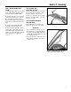
Section 5: Maintenance WARNING Before inspecting, cleaning or servicing the unit, shut off engine, wait for all parts to come to a complete stop, disconnect spark plug wire and move wire away from spark plug. Remove ignition key on electric start models. Failure to follow these instructions can result in serious personal injury or property damage. C E Cutting Edge of Tine F Figure 5-6: Removing single tine. Figure 5-8: Forward clutch belt. (C, Leftside view, no belt cover.
Section 5: Maintenance WARNING Before inspecting, cleaning or servicing the unit, shut off engine, wait for all parts to come to a complete stop, disconnect spark plug wire and move wire away from spark plug. Remove ignition key on electric start models. Failure to follow these instructions can result in serious personal injury or property damage. 2. The coiled part of the forward clutch spring (E, Figure 5-10) measures 2" in length when the Forward Clutch Control levers are not pulled up.
Section 5: Maintenance WARNING Before inspecting, cleaning or servicing the unit, shut off engine, wait for all parts to come to a complete stop, disconnect spark plug wire and move wire away from spark plug. Remove ignition key on electric start models. Failure to follow these instructions can result in serious personal injury or property damage. C I E B D P K O A Figure 5-18 Figure 5-20: Arrow (K) shows insertion point for installing new forward clutch belt.
Section 5: Maintenance WARNING Before inspecting, cleaning or servicing the unit, shut off engine, wait for all parts to come to a complete stop, disconnect spark plug wire and move wire away from spark plug. Remove ignition key on electric start models. Failure to follow these instructions can result in serious personal injury or property damage. pull down on the belt and roll it onto the large, forward-most groove of the transmission pulley (P, Figure 5-20). 7. Reinstall the belt cover. 8.
Section 5: Maintenance WARNING Before inspecting, cleaning or servicing the unit, shut off engine, wait for all parts to come to a complete stop, disconnect spark plug wire and move wire away from spark plug. Remove ignition key on electric start models. Failure to follow these instructions can result in serious personal injury or property damage. BATTERY MAINTENANCE DANGER Use extreme caution when working on or near batteries.
Section 5: Maintenance WARNING Before inspecting, cleaning or servicing the unit, shut off engine, wait for all parts to come to a complete stop, disconnect spark plug wire and move wire away from spark plug. Remove ignition key on electric start models. Failure to follow these instructions can result in serious personal injury or property damage. TILLER ATTACHMENTS The attachments listed below are available for your tiller. The information is the most current at the time this manual was printed.
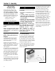
TROUBLESHOOTING Before performing any corrections, refer to the appropriate information in this Manual, or in the Engine Owner’s Manual, for the correct safety precautions and operating or maintenance procedures. Contact your local authorized Engine Service Dealer for engine service. Contact your local authorized equipment dealer or the factory for all other service problems. PROBLEM POSSIBLE CAUSE CORRECTION Engine does not start. 1. Spark plug wire disconnected. 2.
PARTS LIST Models 12211 and 12212 HOOD, BRACKET and DEPTH REGULATOR REF. No. 1 PART No. 1917605 2 3 1100243 2527 4 5 6 7 8 9 10 90038 9811 1100069 9384 9438 9308 1117A DESCRIPTION Tine Hood (Incl. hood flap and Ref.17) ............................................ Lockwasher, 3/8.................................. Bracket–hood & depth regulator (Incl. Ref. No. 9)............................. Hex Flange Screw, 5/16-18 x 5/8* ...... Hex Locknut, 1/4-20 ........................... Hex Hd.
PARTS LIST Models 12211 and 12212 HANDLEBAR ASSEMBLY and CONTROL LEVERS 10 See page 36, Ref. 47, for attachment screw.
PARTS LIST Models 12211 and 12212 HANDLEBAR ASSEMBLY and CONTROL LEVERS REF. No. PART No. 1 2 3 3A 4 5 5A 6 7 8 9 10 13 1918811 9126 1918770 20924 1916784 1186347 9955 1900475001 1100046 9904 9837 1918791 9442 14 9057 DESCRIPTION Handlebars (Incl. Refs. 2, 3 & 3A) ....... Grip ..................................................... Decal, Control Panel ........................... Decal, Model Name/Logo .................... Reverse Clutch Control Cable .............. Height Adjustment Screw ...........
PARTS LIST Models 12211 and 12212 ENGINE, SUPPORT BRACKETS, PULLEYS, BELTS, BELT COVER 36 5 6 1 Reverse Clutch Cable 2 7 3 4 9 10 11 8 13 35 14 16 12 15 16 17 45 49 39 40 41 20 40 35 42 46 18 48 21 45 49 50 20 43 51 38 43 8 22 12 44 9 44 37 37 47 24 25 31 23 26 27 30 3 28 29 36
PARTS LIST Models 12211 and 12212 ENGINE, SUPPORT BRACKETS, PULLEYS, BELTS, BELT COVER REF. No. 1 2 3 4 5 6 7 8 9 10 11 12 13 14 15 16 17 18 19 20 21 22 23 24 25 PART No. ** ** 1917326 1100242 1111696 1904557 1917139 1186391 1108841 1138-1 1916520 9944 9572 1111606 1918731 1916535 1107382 1916725 1100005 1917746 9929 1916728 1916522 1440 1918812 1909404 DESCRIPTION Engine – standard recoil start ............ Engine – electric start ........................ Bracket, Clutch Cable .........................
PARTS LIST Models 12211 and 12212 TRANSMISSION HOUSING, COVERS, SEALS, GASKETS, PLUGS NOTE 1: These screws are a special sealing screw that cannot be reused without risking the loss of transmission oil. If these screws are loosened or removed, they must be replaced with new screws. REF. No. PART No. 1 2 3 4 5 6 9621 9726 97076 1186329 85030 11513 7 8 20694 1916197001 9 10 11 12 13 9467 1916198001 97073 90038 1916273001 DESCRIPTION Oil Seal (Double Lip), Wheel Shaft ...... Pipe Plug, 1/4, ........
PARTS LIST Models 12211 and 12212 DRIVE SHAFT, INPUT PINION SHAFT and GEAR ASSEMBLIES REF. No. PART No. DESCRIPTION QTY. REF. No. MAIN DRIVE SHAFT 1 2 3 4 1714 20718 9301 11603 5 1224-1 5 1224-2 5 1224-3 ... 1325C Bearing, Tapered Roller with Race .... 1 Spur Gear .......................................... 1 Key, 3/16 sq. x 1 ...............................
PARTS LIST Models 12211 and 12212 WHEEL SHAFT, ECCENTRIC SHAFT and TILLER SHAFT ASSEMBLIES REF. No. 1 2 3 ------4 5 6 7 8 PART No. 9621 9511 1166-1 1166-2 1166-3 1166-4 1086 2494 9373 20914 9935 DESCRIPTION Oil Seal .............................................. Retaining Ring (heavy-duty, external) Shim, 1-1/64 I.D., .062" thick ............ Shim, as above, but .030" thick ......... Shim, as above, but .015" thick ......... Shim, as above, but .010" thick ......... Bushing .............................
PARTS LIST Models 12211 and 12212 BOLO TINES, WHEELS 13 NOTE 1: Custom Tilling Tines are available for your tiller. These are special hard-faced tines that are thicker than standard tines. 13 IMPORTANT: Left and right sides of tiller are determined by standing in operator position and facing direction of forward travel. REF. No. 1 2 PART No. 1100043 1270-2A 3 5 7 1733398 1982612 1270-1A 8 -- 1902154010 1901118 DESCRIPTION QTY. Hex Hd. Screw, 3/8-16 x 1-1/4*.......... 16 Bolo Tine-single.
PARTS LIST Models 12211 and 12212 ELECTRIC START ASSEMBLY 30 31 42
PARTS LIST Models 12211 and 12212 ELECTRIC START ASSEMBLY REF. No. PART No. 1 96512 2 2A 3 4 5 6 9462 9248 9009 1475 9224 9552 7 11361 8 1908112 9 1904570 10 11 12 13 14 1904548 96520 96509 96510 1908118 DESCRIPTION QTY. Battery, 12 Volt, 9 Amp (Incl. Ref. 7) ........................................... 1 Battery Cap (yellow) .......................... A/R Battery Cap (white)............................ A/R Vent Tube ..........................................
PARTS LIST Models 12211 and 12212 ROW MARKER ATTACHMENT (See Detail A) ROW MARKER ATTACHMENT – PART # 12589 (Complete – Attaches to Furrower Attachment) DETAIL A MAIN SUPPORT/YOKE ASSEMBLY PART # 1904522001 BUMPER ATTACHMENT 20 19 23 22 21 BUMPER PART #12593 44
PARTS LIST Models 12211 and 12212 ROW MARKER ATTACHMENT & BUMPER ATTACHMENT REF No. PART No. DESCRIPTION QTY. Row Marker Attachment (option) – Part #12589 1 1904522001 2 3 4 1594 1904524001 1904523001 5 9347 6 9786 7 1596 8 9828 9 1100135 --- 1837 --- 12582 --- 12589 Main Support & Yoke Assy– complete. (Incl. Ref. No.'s 10,11,12,13,14,15,16,17 & 18).......... Marker Blade–blade only ................... Marker Arm–main arm ......................
PARTS LIST Models 12211 and 12212 HILLER/FURROWER ATTACHMENT HILLER/FURROWER – PART #12579 (Viewed from front of tiller) REF. No. 1 2 3 4 5 6 7 8 46 PART No. 1900771001 1186098 1177548 9902 9824 1900773001 1900774001 1900772001 DESCRIPTION Furrower Blade .................................. Carriage Bolt, 5/16-18 x 3/4 .............. Star Washer, External Tooth, 5/16..... Plain Washer, 5/16 S.A.E................... Wing Nut, 5/16-18............................. Hiller Wing, left.........................
NOTES 47
CUSTOMER SERVICE INFORMATION Owner Registration Card Please fill out and mail the enclosed owner registration card. The purpose of this card is to register each unit at the factory so that we can provide you with warranty benefits and informational bulletins. Customer Service and Technical Service If you have questions or problems with the unit, contact your local dealer or the factory. (When calling or writing, provide the Model/Serial Numbers of the unit.