YaRD-MaN)/f Operator's Manual 21" Three-in-One Self-Propelled Mower Model 12A-568Q401 IMPORTANT: Read safety rules and instructions carefully before operating equipment. Warning: This unit is equipped with an internal combustion engine and should not be used on or near any unimproved forest-covered, brush-covered or grass-covered land unless the engine's exhaust system is equipped with a spark attester meeting applicable local or state taws (if any).
TABLEOFCONTENTS Content Page Important Safe Operation Practices ................................................................... 3 Slope Gauge ...................................................................................................... 6 Assembling Your Lawn Mower ........................................................................... 7 Know Your Lawn Mower .................................................................................... 9 Operating Your Lawn Mower ............
SECTION1: IMPORTANTSAFEOPERATION PRACTICES This symbol points out important safety instructions which, if not followed, could endanger the personal safety and/or property of yourself and others. Read and follow all instructions in this manual before attempting to operate your lawn mower. Failure to comply with these instructions may result in personal injury, When you see this symbol, heed its warning. DANGER: Your lawn mower was built to be operated according to the rules for safe operation in this manual.
Neveroperatethemowerinwetgrass.Alwaysbe Do not mow slopes greater than 15 degrees as sureofyourfooting,Aslipandfallcancause shown on the slope gauge. seriouspersonal injury. Do not mow on wet grass. Reduced footing could Keepa firmholdonthehandleandwalk,never cause slipping. run.Ifyoufeelyouarelosingyourfooting, RELEASE THEBLADECONTROL HANDLE Children IMMEDIATELY andthebladewillstoprotating Tragic accidents can occur if the operator is not withinthreeseconds. alert to the presence of children.
Check the blade and engine mounting bolts at frequent intervals for proper tightness. Also, visually inspect blade for damage (e.g., bent, cracked or worn). Replace with blade which meets original equipment specifications listed in this manual. Keep all nuts, bolts, and screws tight to be sure the equipment is in safe working condition. Never tamper with safety devices. Check their proper operation regularly.
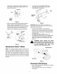
USE THIS PAGE AS A GUIDE TO DETERMINE SLOPES WHERE YOU MAY NOT OPERATE SAFELY. SIGHT AND HOLD THIS LEVEL WITH A VERTICAL TREE _ A POWER POLE ._ _1! A CORNER OF A BUILDING DI_! OR A FENCE POST _oc m¢_ II_l[ l[ _\ 0£?- I _l ....L _ _ _ • _ _# o,," I _._ o CB 03 CF O ! c B o o B o G9 WARNING Do not mow on inclines with a slope in excess of 15 degrees (a rise of approximately 2-1/2 feet every 10 feet). A riding mower could overturn and cause serious injury.
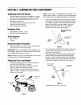
SECTION3: ASSEMBLING YOURLAWNMOWER ToRemoveUnitFromCarton • Remove staples, break glue on top flaps, or cut tape at carton end and peel along top flap to open carton. Remove loose parts included with your unit (i.e., operator's manual, etc.). Cut along corners end lay carton down flat. Remove packing material. Roll or slide unit out of carton. NOTE: Your mower is shipped with the handle in the higher height position.
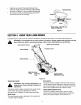
Insert post on cable ties into holes provided on the lower handle. Pull the cable tie tight and trim the excess. See Figure 4. To remove the mulching baffle, lift the rear discharge door on the mower. Remove the mulching baffle. See Figure 6. Cable Tie Deck /I Post _ Mulching Baffle Hole on Lower Handle \ Figure 4 After you have moved the hairpin clips as shown in Figure 2, place one carriage bolt (found in the hardware pack included with your unit) in the upper hole of the right handle mounting brac
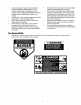
• * Slidethetwohooksofthesidedischarge chute underthehingepinonthemulching ptugassembly asshownin Figure 8. Lower the side mulching plug. Mulching Plug Do not remove the side mulching plug at any time, even when you are not mulching. Hinge Pil ,, t HOO_ IV i/ j /- j (Slide hooks under t aides of hinge pin) Figure 8 SECTION4: KNOWYOURLAWNMOWER Compare Figure 9 with your lawn mower to familiarize yourself with the location of controls and adjustments.
MulchingPlug used to stop engine. Do not adjust WARNING: Thethe throttle control cannot be throttle control with the engine running. Both the mulching baffle and the mulching plug are used only for mulching purposes, instead of collecting the grass clippings in a grass catcher, your mower has the option of recirculating the clippings back to the lawn. This is called mulching. Drive ClutchControl The drive clutch control lever is located on the upper handle and is used to engage the drive.
Be sure that lawn is clear of stones, sticks, wire, or other objects which could damage lawn mower or engine. Such objects could be accidentally thrown by the mower in any direction and cause serious personal injury to the operator and others. For best results, do not cut wet grass because it tends to stick to the underside of the mower, preventing proper discharge of grass clippings, and could cause you to slip and fall. New grass, thick grass or wet grass may require a narrower cut.
AdjustingDriveClutchControl The drive clutch adjustment wheel is located on the drive clutch control handle housing and is used to tighten or loosen tension on the drive cable. Perform this adjustment if the following exists. Handle Lower a. The mower does not propel itself with the drive clutch engaged. b. The mower's drive wheels hesitate with the drive clutch engaged.
SECTION7: MAINTAININGYOURLAWNMOWER • ReplacingRearFlap • • To remove rear flap, cut off the fiat end of the wire rod which secures it to the deck. See Figure 14. Attach the new flap and new rod to deck, bending the ends of the new rod over to secure to deck, • Clean the spark plug and reset the gap to .030" at least once a season or every 50 hours of operation. Spark plug replacement is recommended at the start of each season. Refer to the engine manual for correct spark plug type.
NOTE: When tipping the unit, empty the fuel tank and keep engine spark plug side up. Turn mower on its side making sure that the air filter and the carburetor are up. Hex Bolt / / Bell ' ex Bolt Washer Figure 16 Lube" Eube Figure 15: Lubrication Chart • BladeCare • _lb • Periodically inspect the blade adapter and pulley for cracks, especially if you strike a foreign object. Replace when necessary.
Remove the two shoulder screws which secure the The blade can be tested by balancing it on a round shaft screwdriver. See Figure 17. Remove metal from the heavy side until it balances evenly. It is recommended that the blade always be removed from the adapter for the best test of balance. front drive cover to the mower deck. See Figure 18. Remove the front drive cover from the unit by Lightly pressing inward on the sides of the front drive cover.
SECTION9: TROUBLE SHOOTING GUIDE Trouble ..............._P-ossible Cause(s) Corrective Actions .................. Engine fails to 'l_decontroihandie disengaged_ --1_ Etlgage biacle cont_'oi handiel start 2. Spark plug wire disconnected. 2. Connect wire to spark plug. I 3. Dirtyair cleaner. 3. Refer tothe engine manual 4. Throttle control lever not in correct position. 4. Move throttle lever to FAST or START position. 5. Clean fuel line. 5. Fuel tank empty or stale fuel, 6. BIocked fuelline. 6. Clean.
NOTES: 17
SECTION10: PARTSLIST FORMODEL568 12 8._. 31J 76 / 30 75 74 72-- 23 61 56 54 65 \ 62 "64 NOTE: For painted parts, please refer to the list of color codes below. Please add the applicable color code, wherever needed, to the part number to order a replacement part. For instance, if a part numbered 700-xxxx is painted Yard-Man Green, the part number to order would be 700-xxxx-0665.
Model568 Part No. 4. 5. 6. 7. 8. 9. 10. 11. 12. 13, 14. 15. 16. 17. 18. 19. 20, 21. 22. 23, 24. 25. 28. 29. 30. 31, 32. 33. 34. 35. 36. 37. 38. 39. 40. 41. 42.
Model568 51 39 X 52 47 \ \ 53 \ 46 ....
Model568 Ref. No 1, 2. Part No. 712-3025 E _736-0425 Description Hex Jam Nut 5/16-24 ][Ref.No_ Part No. Description 29. 618-0298A Transmission Assembly (Includes Ref. # 1to Ref. #30) Bell Washer .325 x .930 x .045 3. 756-1042 Pulley. 3.82 x .313 x .68 30. 732-0708 Bearing Retainer 4. 736-0425 Bell Washer .325 x .930 x .045 31. 741-0604 Bearing Sleeve .50 I.D. Lock Nut 1/4-28 32. 748-0355 Bearing Support 33. 738-0447 Wave Washer 1.5 x 1.0 x .029 34. 782-0512B RH Height Adj.
MANUFACTURER'S LIMITED WARRANTY FOR: YaRD-MaN The limited warranty set forth below is given by MTD PRODUCTS INC ("MTD") with respect to new merchandise purchased and used in the United States, its possessions and territories. MTD warrants this product against defects in material and workmanship for a period of two (2) years commencing on the date of original purchase and will, at its option, repair or replace, free of charge, any part found to be defective in material or workmanship.