Safe Operation Practices • Set-Up • Operation • Maintenance • Service • Troubleshooting • Warranty L Self Propelled Mower m Model Series 980 MTD LLC, P.O. BOX 361131 CLEVELAND, OHiO 44136-0019 PrintedIn USA FormNo.
1 ToTheOwner ThankYou Thank you for purchasing a Lawn Mower manufactured by If you have any problems MTD LLC. It was carefully engineered to provide excellent performance when properly operated and maintained. Please read this entire manual It instructs prior to operating your machine. persons who will operate address and mailing the equipment.
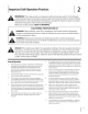
2 importantSafeOperationPractices WARNING: This symbol could endanger all instructions points out important the personal safety and/or in this manual with these instructions before property attempting may result in personal When you see this symbol. safety instructions of yourself to operate which, if not followed, and others. this machine. Read and follow Failure to comply injury.
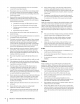
12. Amissing ordamaged discharge cover cancause blade contact orthrown object injuries. 13. Many injuries occur asaresult ofthemower beingpulled overthefootduring afallcaused byslipping ortripping. Donotholdontothemower ifyouarefalling; release the handle immediately. 14. Never pullthemower back toward youwhileyouare walking. Ifyoumustback themower away fromawallor obstruction firstlookdownandbehind toavoid tripping andthenfollowthese steps: a. Stepback frommower tofullyextend yourarms. b.
Service 3. Check the blade and engine intervals To avoid personal care in handling injury or property damage gasoline. Gasoline is extremely can ignite. Wash your skin and change flammable clothes original 3. Use only an approved Never fill containers gasoline container. inside a vehicle 4. Remove gas-powered equipment Keep all nuts, bolts, and screws tight equipment 7. trailer and refuel it on the ground.
SparkArrestor Notice Regarding Emissions Engines which are certified to comply with California and federal EPA emission regulations for SORE (Small Off Road Equipment) are certified to operate may include the following Modification (EM), Oxidizing Injection on regular emission unleaded control gasoline, and internal combustion engine and should not be used WARNING: This machine is equipped with an on or near any unimproved forest-covered, brush i_ll systems: Engine Catalyst (OC), Secondary A
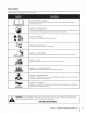
Safety Symbols This page depicts and describes safety symbols that may appear machine before attempting to assemble and operate. on this product. Read, understand, and follow all instructions on the READ THE OPERATOR'S MANUAL(S) Read, understand, assemble and follow all instructions in the manual(s) before attempting to and operate DANGER -- ROTATING BLADES To reduce the risk of injury, keep hands and feet away. Do not operate or grass catcher is in its proper place.
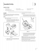
co Sight and hold this level with a vertical tree... -4 5 Z I ,_ or a corner of a building... i i Z __ I i I I O ' FOldo, 5 ' Z "o or a fencepost ', diine , --Lepre_n tsa15 o -4 I I 15 ° Usethis page as a guide to determine slopes where you may not operate safely. WARNING: Do not operate (a rise of approximately mowers up and down up and down slopes. your lawn mower on such slopes. Do not mow on inclines with a slope in excess of 15 degrees 2-1/2 feet every 10 feet).
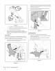
3 Assembly& Set-Up Contents of Carton One Lawn Mower One Side Discharge One Lawn Mower One Grass Catcher Chute Operator's One Engine Operator's 2. without Fill up gasoline and oil as instructed manual BEFORE operating One Bottle Manual of Oil Manual Assembly NOTE:This unit is shipped One Grass Catcher Adapter gasoline or oil in the engine. in the accompanying Locate the hairpin clip on the weld pin on each side of lower handle. a. engine Remove hairpin clip from this hole.
Replacewithgrassbagadapter, 2. adapter whilemakingsurethefrontlipof goes under the edge of the deck. Secure with wing nuts previously removed. Lift chute door on the grass bag adapter 3. bag onto the adapter. and slide grass See Fig. 3-5. f Figure3-3 a. Holdblade control against upperhandle. b. Pullstarterropeoutoftheengine.Release bladecontrol. c. Slipstarter ropeintoropeguide. 4. Attach cables tothelowerhandle withthecable ties already onthelowerhandle.
DriveControl Adjustments The adjustment CuttingHeight The cutting housing height adjustment lever is located above the rear left wheel. See Fig. 3-7A insert. wheel is located and is used to tighten have to adjust the drive control 1. The mower in the drive control handle or loosen the drive belt. You will if any of the following happens: does not propel itself with the drive control drive wheels hesitate with the drive control engaged. 2. The mower's engaged.
4 Controls and Features F Cutting Height Adjustment Lever Recoil Starter Side Discharge Chute Figure 4=1 BladeControl The blade control SideDischargeChute is attached to the upper Depress and squeeze it against the upper handle of the mower. handle to operate the Assembly unit. Release it to stop engine and blade. Never attempt to bypass its operations. ARNING: This blade control is a safety device. _ _i height adjustment rear wheel.
Operation Starting Engine WARNING: Be sure no one other than the operator engine or operating mower. Never run engine is standing near the lawn mower while starting indoors or in enclosed, poorly ventilated areas. Engine exhaust contains carbon monoxide, an odorless and deadly gas. Keep hands, feet, hair and loose clothing away from any moving parts on engine and lawn mower. Refer to engine manual for help with the engine. 1.
Maintenance & Adjustments 2. Maintenance Lubricate the wheels and casters at least once a season with light oil (or motor oil). If wheels are removed for any reason, lubricate the axle bolt and inner surface of the General Recommendations wheel with light oil. See Fig. 6-1. Always observe maintenance. safety rules when performing any 3.
Engine Care Replacing RearFlap A list of key engine performance accompanying Maintain maintenance by the mower jobs required for good To replace is given below. Follow the engine manual for a detailed oil level as instructed in engine manual. Service air cleaner every 25 hours under normal Clean every few hours under extremely 1. list and instructions. rear flap, proceed as follows: To remove rear flap, lift rear door, remove screw, and press flap in on either side to remove from hole.
7 Service 81adoCare 5. Lubricate the engine the blade adapter WARNING: sharpening When removing or replacement, the cutting protect blade for inspect the blade adapter strike a foreign object. Replace when below for blade service. 1. for cracks, especially necessary. part number) Disconnect spark plug boot from spark plug. Turn mower on its side making sure that the air filter and the carburetor are facing up. 2. operating faces the ground position.
Troubleshooting Problem Engine Fails to start Cause 1. Remedy Blade control disengaged. 2. Spark plug boot disconnected. 2. Connect wire to spark boot. 3. Fuel tank empty or stale fuel. 3. Fill tank with clean, fresh gasoline. 4. Engine not primed (if equipped with primer). 4. Prime engine as instructed section. in the Operation 5. Faulty spark plug. 5. Clean, adjust gap, or replace. 6. Blocked fuel line. 6. Clean fuel line. Z Engine flooded. Z Waita few mmutes to restart, butdo not prime.
Problem Cause Uneven cut 1. Wheels not positioned Remedy correctly. 1. Place all four wheels in same height (if equipped 2. Dull blade. i : SECTION 8 -- TROUBLESHOOTING with individual position height adjusters). 2. Sharpen or replace blade.
9 19
2 \ ModelSeries980 13/ ............................
ModelSeries980 Ref No. 1 Ref No. Part Number Lever 22 710-0654A Seres Screw 3/8-16 x 1.00 Lever Assembly 23 736-3010 Washer, Flat, .407 x .812 x .
ModelSeries980 25 14 12
ModelSeries980 Ref NO. 1 Ref I Part Number 914-0474 Description No, I Part Number Description Cotter Pin 29 682-7528-0637 741-0324A Flge Bearing .506 ID x .590 Lg Chain Cover Assembly 2 710-1652 Screw 1/4-14 x .825 30 3 936-0264 Flat Washer.330 31 682-7526-0637 Transmission Axle Assembly 4 914-0104 Cotter Pin 32 918-0263A Transmission Ass'y Complete 33 734-1857 Wheel 7 x 2 ID x.630 OD 5 932-0306A Compression 6 734-2044 Wheel, 9 x 2.
MANUFACTURER'S LiMiTED WARRANTY The limited warranty set forth below is given by MTD LLC with respect to new merchandise purchased and used in the United States and/or its territories and possessions, and by MTD Products Limited with respect to new merchandise purchased and used in Canadaand/ or its territories and possessions (either entity respectively, "MTD").