TWO STAGE GAS SNOW THROWER MODEL DB7659B-22 Questions, problems, missing parts? If you have questions or need technical support, call the Amerisun customer service department at 1-800-791-9458 or visit Amerisuninc.com and e-mail support@amerisuninc.com. WARNING! Read and follow all safety rules and instructions in this manual before attempting to operate this machine. Failure to comply with these instructions may result in personal injury. Save these instructions.
TABLE OF CONTENTS Safety....................................................................................................................................................... 2 Feature Identification ................................................................................................................................ 6 Box Contents ............................................................................................................................................ 7 Assembly ...............
SAFETY This symbol points out important safety instructions which, if not followed, could endanger the personal safety and or property of yourself and others. Read and follow all instructions in this manual before attempting to operate this machine. Failure to comply with these instructions may result in personal injury. WARNING! This machine was built to be operated according to the safe operation practices in this manual.
• Exercise caution to avoid slipping or falling, especially when operating in reverse. • Stay alert, watch what you are doing and use common sense when operating your Snow Thrower. • Do not use your Snow Thrower while you are tired or under the influence of drugs, alcohol, medication. A moment of inattention while operating the Snow Thrower may result in severe bodily injury. • NEVER LEAVE YOUR RUNNING SNOW THROWER UNATTENDED. Stop the engine.
• If the machine should start to vibrate abnormally, stop the engine, disconnect the spark plug wire and ground it against the engine.Inspect thoroughly for damage. Repair any damage before starting and operating. • Disengage all control levers and stop engine before you leave the operating (behind the handles). • Wait until the auger /impeller comes to a complete stop before unclogging the chute assembly, making any adjustments, or inspections. • Never put your hand in the discharge or collector openings.
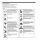
Safety Symbols This page depicts and describes safety symbols that may appear on this product. Read, understand and follow all instructions on the machine before attempting to assemble and operate.
FEATURE IDENTIFICATION TECHNICAL SPECIFICATIONS Clearing Width: DB7659B 22 inches Clearing Height: 16 inches 4 Forward and 2 Reverse Speeds Engine Displacement: 196 cc, 4 stroke A - Drive Control Handle B - Speed Control Lever C - Auger Control Handle D - Chute Rotation Handle E - Engine F - Skid Shoe G - Augers H - Impeller I - Snow/Ice Clean Out Tool J - Chute Assembly - 6
A. Drive Control Handle Shave Plate (not shown) Located on the right side of the upper handle, the Drive Control is used to engage and disengage the drive wheels. Squeeze the Drive Control handle against the upper handle to engage the wheels; release to disengage. B. Speed Control Lever The Shave Plate maintains contact with pavement as the snow thrower is propelled, allowing snow close to pavement's surface to be discharged.
2. Attach the chute rotation bar to the mount bracket onto the chute housing using two hex screws, washers and locknuts. Tighten fasteners securely. NOTICE: Make sure all fasteners are tightened before starting the machine. 3. Slide the upper chute crank rod through the mounting hole under the control panel and into the lower chute crank rod. 2. Attached the upper handle to the lower handle using four (4) knobs, washers and bolts. Handle Assembly 1. Attach the lower handles using four (4) bolts.
NOTICE: Do not bend or kink the control cables. The cables should be routed under the handle assembly and not wrapped around the handle or knobs. The cables must move freely and not bind. 3. Secure the speed control cables to the handle with provided clips. Note: Do not secure the auger or drive control cables with the clips. Skid Shoe Installation and Adjustment 1. Locate the pair of skid shoes from parts bag and remove the bolts. 2.
4. Place a spacer board on the ground underneath the auger shave plate between the skid shoes. The thickness of the board should be the same as the height above the ground you wish to raise the auger shave plate. The skid shoes should not touch the board. 5. With the two (2) nuts loose allow the skid shoe to slide to the ground then tighten the nuts to secure the skid shoe. OPERATION PLEASE REFER TO ENGINE MANUAL (SEPARATE DOCUMENT) FOR ENGINE OPERATION INSTRUCTIONS.
Auger and Drive Controls Drive Speed Control Lever 1. To engage the auger, press down on the auger control handle (left side handle). Move the drive speed control lever to the desired speed. There are six (6) settings: four (4) forward speeds and two (2) reverse speeds. 1 is the slowest forward speed and 4 is the fastest forward speed. R1 is the slowest reverse speed and R2 is the fastest reverse speed. 2. To engage the drive, press down on the drive control handle (right side handle).
Chute Discharge Angle Adjustment WARNING! Always disengage the drive and auger control handles before making adjustments. Make sure the augers are stopped and the machine is not moving. The angle of the chute deflector controls the discharge distance of the snow. Raising the angle will increase the distance. Lowering the angle will decrease the distance. Adjust the chute outlet to the desired direction. Turn the chute rotation handle clockwise or counter-clockwise until the desired position is reached.
2. Stop the auger by releasing the left control handle. 3. Set the engine switch to the OFF position. See ENGINE manual for stopping procedures. 4. Remove snow from all Snow Thrower surfaces including the auger housing and chute areas. Clearing Restrictions If the snow discharge chute or auger housing becomes clogged STOP the engine, and make sure that all rotating parts have come to a complete stop. Remove the spark plug cap from the spark plug.
Auger or Impeller Jams WARNING! The auger and impeller rotate at fast speeds which can cause harm or even amputation to a person's body parts. Even if you do not see the auger or impeller rotating, it may start at any time if the engine is running. The chute clean-out tool is fastened to the top of the auger housing with a mounting clip and a cable tie at the factory. Cut the cable tie before operating the snow thrower. 1. Always turn OFF the engine before attempting to clear any clogs or jams. 2.
Note: The upper cable end must be in the upper single center hole of the adjustment plate. Do not change the position of the upper cable. 3. Slide up the slip cover to access the adjustment plate. 5. Connect the upper cable to the control handle. 6. Start the engine and engage the drive control handle to test the operation of the drive engagement. Note: With the drive control handle at the full released position, the cable should be barely tight.
1. With the engine running engage the drive control handle and move the speed control lever between F1 and R1 to determine which way the cables need to be adjusted. Release the drive control handle when shifting between gears. 2. Loosen the jam nuts on each cable (only one or two threads) and move each cable up and down as required until a positive direction change is achieved when the lever is shifted between F1 and R1. This may take multiple attempts to find the exact setting. 3.
(1 to 9). Only move the lower cable diagonally one hole at a time from its original position. Note: The upper cable end must be in the upper single center hole of the adjustment plate. Do not change the position of the upper cable. 1 2 3 4 5 6 – – – – – – Upper Auger Cable (Always in upper center hole) Adjustment Plate lower Auger Cable Cable Pulley Adjustment Plate Lower Cable Opening Slip Cover 1. Stop the engine. 2. Disconnect the upper cable from the auger control handle. 5.
3. Loosen the belt guide pin hex head screw (installed on engine crankcase) and rotate the pin away from the pulley. 4. Left Side - Loosen the hex screws attaching the auger housing to the main frame. 6. Remove the belt from the drive pulley while pulling the right side of the auger housing away from the main frame just enough to access the belt and auger pulley. 7. Push the auger tension pulley arm to move the auger brake, away from the belt to allow removal of the belt. 5.
pulley while pulling the auger housing into position with the main frame. 1 – Auger Brake 8. Remove the auger belt. Auger Belt Installation WARNING! Entanglement Hazard - Before performing any service procedures, make sure the engine is off and remove the spark plug wire from the spark plug to ensure the engine cannot accidently start. NOTICE: Before installing the auger belt, see Auger Belt and Related Component Inspection and repair or replace any components as required. 4.
WARNING! Ensure the belt cover is installed and all safety guards are in place before the engine is started and at all times when the engine or machine are operating. 8. Install belt cover using 2 hex head screws.Make sure the auger cable is routed outside the belt cover as shown.
Storage Cleaning WARNING! Never store your Snow Thrower for extended periods of time with fuel in the tank. Fuel stabilizer can be added to the fuel to extend its shelf life for storage. 1. To clean your Snow Thrower, use a damp cloth and mild detergent on the surfaces only. Never get soap or water inside the working mechanisms of your Snow Thrower. Note: Do not clean with water. Water will freeze due to low temperature and damage the machine.
TROUBLESHOOTING Problem Possible Causes Remedy WARNING - Before attempting to make any inspections, repairs or adjustments, stop the engine, wait for all moving parts to stop moving and carefully disconnect the engine spark plug wire. If tipping or turning the snow blower is required for any inspection or repair, first wait until the engine is cool to the touch and then drain the engine of all fuel and oil into suitable containers and store or dispose of in a proper manner.
Drive System No forward or reverse drive movement when drive handle engaged Drive speed control stuck in gear or wont change gears Drive speed control allows only one direction forward or reverse Drive engaged when drive control handle released 1 Drive control cable loose, broken or binding 1 Repair or adjust drive control cable and adjust tension, see Auger and Drive Cable Adjustment 2 Drive belt loose or damaged 2 Check drive belt tension pulley for damage or incorrect tension, repair as necessary.
WARRANTY ONE YEAR WARRANTY WARRANTY For one year from date of retail purchase within U.S.A., the manufacturer will, at its option, repair or replace, for the original purchaser, free of charge, any part or parts found to be defective in material or workmanship.