OPERATOR’S MANUAL Single-Stage Snow Thrower Models 140 150 E150 E162 E172 IMPORTANT: Read safety rules and instructions carefully before operating equipment. Warning: This unit is equipped with an internal combustion engine and should not be used on or near any unimproved forest-covered, brush-covered or grass-covered land unless the engine’s exhaust system is equipped with a spark arrester meeting applicable local or state laws (if any).
TABLE OF CONTENTS Content Page Important Safe Operation Practices ......................................................................................... 3 Assembling Your Snow Thrower .............................................................................................. 5 Know Your Snow Thrower........................................................................................................ 7 Operating Your Snow Thrower......................................................................
SECTION 1: IMPORTANT SAFE OPERATION PRACTICES WARNING: This symbol points out important safety instructions which, if not followed, could endanger the personal safety and/or property of yourself and others. Read and follow all instructions in this manual before attempting to operate this machine. Failure to comply with these instructions may result in personal injury. When you see this symbol—heed its warning.
11. 12. 13. 14. 15. 16. 17. 18. 19. 20. Your Responsibility: • Restrict the use of this power machine to persons who read, understand and follow the warnings and instructions in this manual and on the machine. DANGER 1. KEEP AWAY FROM ROTATING AUGER CONTACT WITH AUGER CAN AMPUTATE HANDS AND FEET. 10. Never tamper with safety devices. Check their proper operation regularly. 2. Disengage all clutch levers and stop engine. Wait until the auger/impeller come to a complete stop.
SECTION 2: ASSEMBLING YOUR SNOW THROWER NOTE: This Operator’s Manual covers several models. Snow thrower features vary by model. Not all features discussed in this manual are applicable to all snow thrower models. Upper Handle Contents of Carton Before beginning installation, remove all parts from the carton and compare them to Figure 1. Carton contents are listed below with part numbers in parentheses.
NOTE: The upper hole in the control handle provides for adjustment in belt and cable tension. Refer to page 9 of this manual for instructions. Eye Bolt Installing the Chute Directional Control’s Eye Bolt (on models so equipped) Hex Nut Cross Bar To install the upper crank of the chute directional control, proceed as follows: • • • Saddle Washer Thread one of the hex nuts (they are interchangeable) included in the snow thrower’s hardware pack all the way onto the eye bolt.
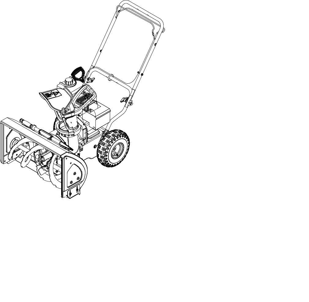
SECTION 3: KNOW YOUR SNOW THROWER Discharge Chute Fuel Cap Primer Spark Plug Cover Ignition Key Starter Handle Electric Starter Button (If So Equipped) Choke Lever Control Handle Chute Directional Control Upper Handle Shave Plate Electric Starter Plug (If So Equipped) Auger IMPORTANT: This unit runs on a mixture of gasoline and oil. Do NOT operate the snow thrower without first reading the Tecumseh Engines operator’s manual for instructions regarding proper fuel and engine oil.
Discharge Chute Shave Plate The pitch of the discharge chute controls the angle at which the snow is thrown. Loosen the wing knob on the side of the discharge chute before pivoting the discharge chute upward or downward. Retighten the knob once the desired position has been achieved. The shave plate scrapes along the pavement as the snow thrower is propelled, allowing the snow close to the pavement’s surface to be discharged.
• • After clearing snow, allow the engine to run for an extra few minutes before storing to help dry any moisture on the engine. To stop the engine: Turn the ignition key counterclockwise to the OFF position. Refer to Ignition Key on page 7. Remove the key form the snow thrower’s ignition switch before storing. IMPORTANT: Keep the ignition key in a safe place. The engine can not be started without it. • • Wipe all the snow and any moisture which has formed, from the unit.
Shave Plate • To check the adjustment of the shave plate, place the unit on a level surface. The wheels, shave plate and augers should all contact the level surface. Note that if the shave plate is adjusted too high, snow may blow under the housing. If the shave plate wears out excessively, or the unit will not selfpropel, the shave plate may be adjusted too low. NOTE: On new units or units with a new shave plate installed, the augers may be slightly off the ground.
• Replacing the Auger’s Rubber Paddles Reattach the belt cover with the five hex screws removed earlier. The snow thrower auger’s rubber paddles are subject to wear and should be replaced if any signs of excessive wear is present. Replacing the Shave Plate The shave plate is subject to wear and should be checked periodically. There are two wearing edges and the shave plate can be reversed after one side wears out. To replace (or reverse) the shave plate, proceed as follows:.
SECTION 8: TROUBLESHOOTING GUIDE Problem Cause Engine fails to start Remedy 1. 2. Key not in ignition switch or not in ON position. Fuel tank empty, or stale fuel 1. 2. 3. 4. 5. Blocked fuel line Spark plug wire disconnected Faulty spark plug 3. 4. 5. 1. 2. Unit running on choke Fuel line blocked, or stale fuel 1. 2. 3. 4. Water or dirt in fuel system Carburetor out of adjustment 3. 4. Move choke lever to off position. Clean fuel line and fill tank with fresh, clean gasoline.
NOTES 13
SECTION 10: PARTS LIST 12 20 13 15 3 21 7 23 19 6 27 38 24 37 26 22 7 8 25 39 17 11 34 36 1 18 16 18 8 22 5 35 40 10 4 2 22 29 28 31 9 14 33 30 32 9 31 9 14
Models 140, 150, E150, E162 & E172 REF. NO. 1 2 3 4 5 6 7 8 9 10 11 12 13 14 15 16 17 18 19 20 21 22 23 24 25 26 27 28 29 30 31 32 33 34 35 — 36 37 38 39 40 PART NO.
Models 140, 150, E150, E162 & E172 29 74 26 12 28 20 6 60 17 13 3 15 27 25 14 31 19 5 24 66 18 57 21 52 7 16 71 69 22 1 38 30 6 52 49 58 7 53 50 45 67 2 6 4 65 47 22 4 70 32 37 34 33 9 23 62 35 56 55 50 59 22 42 54 68 40 43 7 61 11 8 41 64 51 10 72 46 36 73 48 63 44 72 73 16 39
Models 140, 150, E150, E162 & E172 REF. PART NO. NO.
NOTES 18
MANUFACTURER’S LIMITED WARRANTY FOR: The limited warranty set forth below is given by MTD LLC with respect to new merchandise purchased and used in the United States, its possessions and territories. MTD LLC warrants this product against defects for a period of two (2) years commencing on the date of original purchase and will, at its option, repair or replace, free of charge, any part found to be defective in materials or workmanship.