
Programming instructions


NC Programming 17VRS Motion Blocks
4-53
DOK-MTC200-NC**PRO*V17-ANW1-EN-P
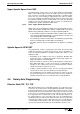
Example NC program - face machining
X1
10
20
30
40
50
60
70
10
[P8]
[P7]
[P6]
[P5][P4]
[P3]
[P2]
[P1]
Y
1
70 60 50 40 30 20
Fig. 4-52: Face machining with coordinate transformation
T12 M6 ;Tool change of driven tool
M89 ;Engage driven tool
S2 3500 M203 ;Driven tool ON
G00 G17 G54 G48 Z100
X140 C0 ;Home position for the change
G31 ;Activate coordinate transformation
G54 G90 G06 G08 G48 ;Home position
G00 G42 G94 X1 60 Y1 20 ;[P1] starting point of machining
G01 Z-0.5 F500 ;Infeed Z axis
X1 20 Y1 60 F400 ;[P2] 1st straight line
X1 -20 ;[P3] 2nd straight line
X1 -50 Y1 30 ;[P4] 3rd straight line
G02 X1 -50 Y1 -30 I-50 J0 ;[P5] Semicircle in CW direction
G01 X1 -20 Y1 -60 ;[P6] 4th straight line
X1 20 ;[P7] 5th straight line
X1 60 Y1 -20 ;[P8] 6th straight line
Y1 20 ;[P1] 7th straight line
G00 Z10 ;Z axis to safety distance
G30 ;Cancel coordinate transformation
G54 G48 G00 X140 ;Home position
Z200 ;Withdraw Z axis
M90 ;Disengage driven tool
M30 ;Return to program beginning
NC program