
Programming instructions


NC Programming 17VRS Motion Blocks
4-55
DOK-MTC200-NC**PRO*V17-ANW1-EN-P
NOTE
Before lateral cylinder surface machining is activated, the
activated machining plane must be spanned by at least
one rotary axis. This is possible using G20, free plane
selection.
CAUTION
When lateral cylinder surface machining is activated or
de-activated, the CNC de-activates all zero offsets and
sets G53.
If diameter programming (G16) is selected during lateral
cylinder surface machining, the CNC interprets all posi-
tion values of the axis with axis meaning X as diameter
specifications.
Please refer to the „Free plane selection and lateral cylinder surface ma-
chining“ description in Folder 5 for further and supplementary information
about lateral cylinder surface machining.
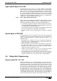
Example NC program - lateral cylinder surface machining
Fig. 4-54: Lateral cylinder surface machining with coordinate transformation
:
Milling contour ‘letter 1’
N0008 G55 G15 G94 G97 G6 G8 S2 3000 M203
N0009 G0 C0
N0010 G20 Z0 C0 X0 Free plane selection
N0011 G32 RI 36.5 Lateral cyl. surface machining ON
N0012 G55 G48 Z1-36.15
N0013 Y1 25 Z1-36.15
N0014 X38
N0015 G1 X36 F150
N0016 G42 Y1 25 Z1-42 F297
N0017 Y1 50 Z1-42
N0018 G2 Y1 54.2426 Z1-30.7574 I-35 J50
N0019 G1 Y1 34.2426 Z1-10.7574
N0020 G2 Y1 25.7574 Z1-19.2426 I-15 J30
N0021 G1 Y1 36.5147 Z1-30
N0022 Y1 5 Z1-30
N0023 G2 Y1 5 Z1-42 I-36 J5
N0024 G1 Y1 25 Z1-42
N0025 G0 X38
N0026 G30 Lateral cyl. surface machining OFF
:
Detailed description
NC program